Making a builtup crankshaft

Home Model Engine Machinist Forum

Help Support Home Model Engine Machinist Forum:

This site may earn a commission from merchant affiliate links, including eBay, Amazon, and others.
Joined
Nov 11, 2010
Messages
13
Reaction score
0
Hi I am new here, retired old guy living in Canada.
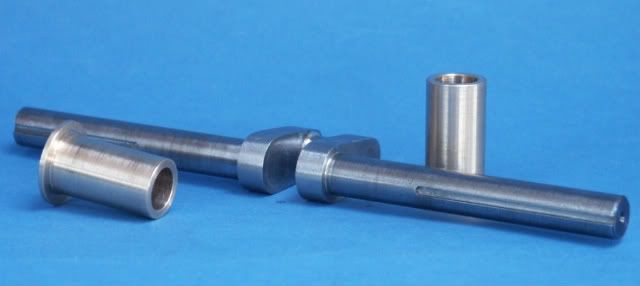
I have had the castings to build a 1/3 scale Fairbanks Morse farm engine for about 10 years now. How to build the crankshaft has been one of many reasons for the delay, unless I get a move on I will run out of years to finish it.
So I am asking for any and all help, (by the way it is a 1.5" bore 2.0" stroke) that likely makes it rather large compared to many of the projects I read of on this board. The plans call for Loctite and tapered pins to secure the joints but nothing regarding the type surface finish clearances and I am sure many more that have not jet crossed my mind.

Thanks in advance for all help Jack
 
I built up a crank with lock tight and tapered pins. I didn't leave much clearance (slip fit)? I assembled the crank on the one piece shaft then cut out the center shaft afterward. The crank shaft is in the pic.

102.JPG
 
Hi Jack,
I am currently building a 1/3 Galloway engine. It also has a built-up crankshaft. The journals are .625 diameter. The designer recommends assembling the pieces with the main shaft as a through rod, silver soldering the joints, pinning with tapered pins and then cutting out the center section. The flywheels on this engine are 10.25 inches in diameter so I don't know if I would trust taperd pins to carry the whole load. With the intermittent firing it puts quite a torque load on the crankshaft.
gbritnell
 
Jack, I just made several built-up crank shafts after a failed attempt at machining one from solid. Here's a link to the problem and final solution that I came up with. Start with reply #31 through to reply #57. I used drill rod. It has a very good surface finish, and all the web holes were drilled and reamed for a snug slip fit. #609 Loctite is the right stuff for this type of fit, and tapered pins might be a little better than the strait dowel pins that I'll be using. By the way, I spend my summers up in Eastern Ontario Canada, and absolutely love it.

Good luck with your crank.

http://www.homemodelenginemachinist.com/index.php?topic=11257.15

-MB
 
I just finished a built up crank for the Hired Man I am working on. Silver soldered and pinned all parts together. I found a lot of info on this site...
Don

IMG_20101204_125124.jpg
 
Hi Guy's,
Here's different status of the assembly of the cranshaft
The most difficult job, follow me, is the distance between the 2 holes
So check it twice before drilling


141010.JPG


121010.JPG


161010.JPG


161010 (2).JPG
 
I made one with a 2.5" stroke for a Carlisle+Finch "model" engine from 3/4" ground stock and mild steels webs. All shafts heat shrunk onto throws and pinned perpendicular (4 places) with reamed and press fit ground stock pins. Tig welded the outer surfaces where the pins came to flats and where the crank pin intersected the throw. Milled out the center web and then tig welded the inside joint. Had a slight bit of spring back which was easily remedied with a few whacks with a soft blow hammer. All surfaces skim cut- here are results before final sanding and finishing. Will fill the weld pit showing before painting the throws. When installed with keys and 10" flywheels, it runs true within 2-3 thou .

crankCF.jpg
 
I recently did this one for a 1/5th IHC Famous, its 7/16 rod and 5/16 webs all mild steel. I silver soldered (silver brazed) it then drilled for pins with lightly CSh holes and then peined the pins over, once filed to profile the pins don't show. I will be using the same method on a 1/2scale Domestic that I also have to do.

PICT0132.jpg


Jason
 
Jason

When you build a crankshaft like the one pictured how much of a gap do you leave for silver solder (if any at all)? Are they reamed for a slip fit then brazed with no additional turning?

Beautiful work on your engines!

Brad
 
On that crank I think I just driled 1/4, 3/8 and then plunge cut with a 7/16 2 flute slot drill, the bright mild steel (CRS) is usually a thou or two undersize which gives the solder somewhere to run.

No other turning except a very fine cut to remove most of the solder fillet from the internal corners.

J
 
I'll put a small bevel around the hole to form a trough for the solder to melt into as well.
 

Latest posts

Back
Top