Making a Boiler for a 3 1/2" Gauge Locomotive

Home Model Engine Machinist Forum

Help Support Home Model Engine Machinist Forum:

This site may earn a commission from merchant affiliate links, including eBay, Amazon, and others.
lordedmond said:
. . . I am assuming girder stay on the top of the fire box wrapper to the outer wrapper ;D they are fun to solder up
They ARE fun to solder up . . . or at least were. I was having so much fun soldering the girder stays on larger fireboxes I felt I needed to do something to take some of the fun out of it. So I decided I would drill a couple of small feed holes in the shell over each stay flange, at least at the most inaccessible sections, and feed solder to those areas from the outside. I finish up by making sure there is a puddle of solder left in the feed holes. That did the trick and now I'm not having any fun at all.
 
Yes it does use girder stays:- :-\

Talking to the inspector last week he said it would be acceptable to use a couple of rows of round stays, they would have to be 1 3/4 " long I can't find a source of rivets that long so I was wondering about making them from 3/16" copper rod I can thread this and screw them through the outer fire box into the inner that way they will stay in place whilst they are soldered, I've put the decision on hold until I talk it over in more detail with the inspector at the weekend.

Thanks for you input and comments Lads

Stew


easily solved

use some bronze rod and squash the end ( a good old clout with a hammer) that will stop them falling out

no need to thread them at all SS as per normal

Stuart
 
I like that idea Stuart.

Well the soldering is on the back burner (pun) :D until I gat the work done so far, checked out by the boiler inspector. So did a bit of shop maintainance.
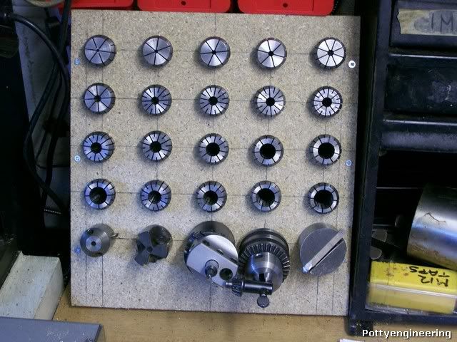
Nocked this tooling rack up,

100_3841.jpg


This frees up some space which in my small shop is at a premium.

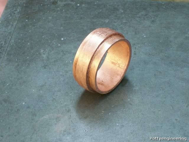
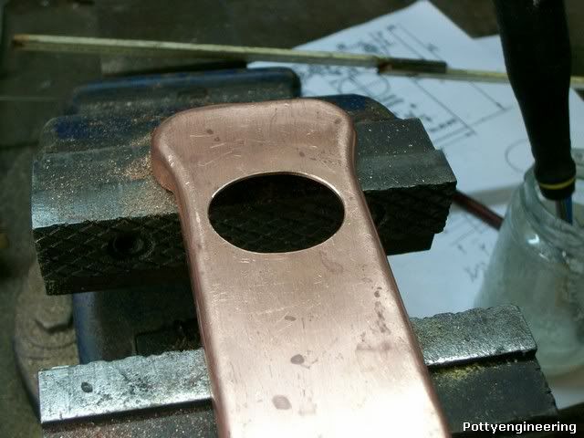
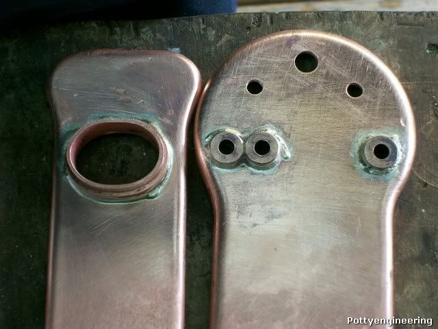
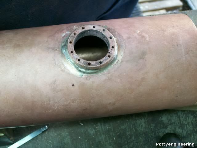
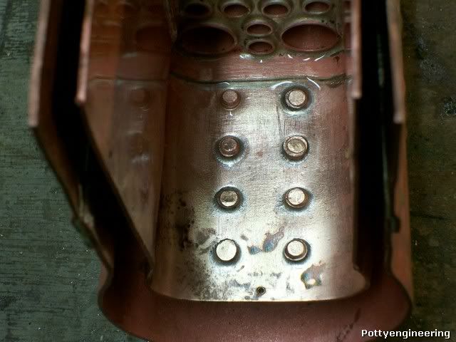
Then did one or two machining jobs for the boiler first up the "Fire Hole" no not the sort you get after a night down the pub and a curry, the sort they shuvel the coal through.

Its made from a bit of thick wall copper tube:- a short step turned on each end so that you've got a 1/4" collar, a quick anneal and a soak in the pickle.

100_3836.jpg


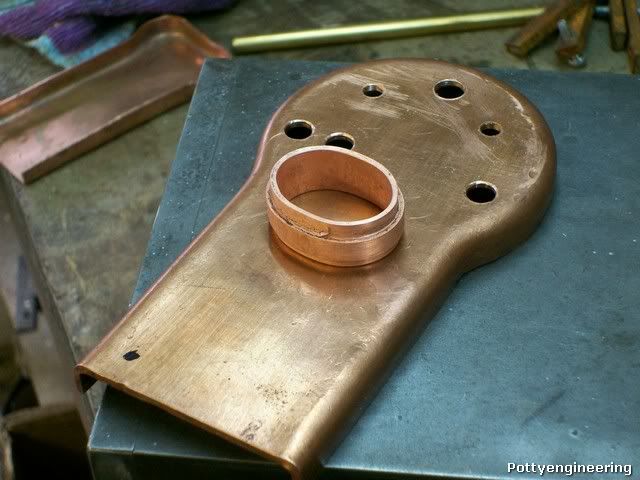
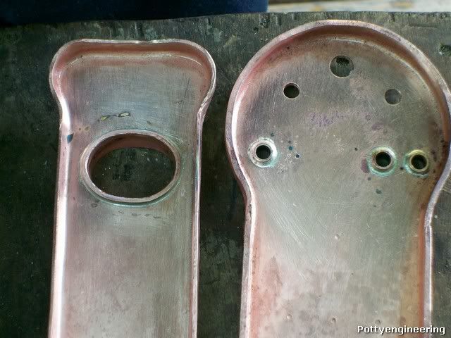
Then a squeeze in the vice to make it oval and here it is on the backhead.

100_3839.jpg


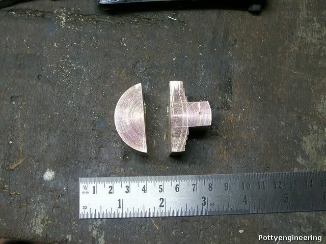
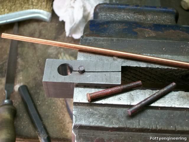
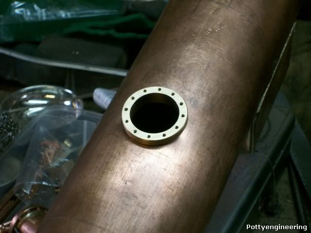
Next up the bush for the water gauge, for some reason there is no dimensioned drawing for it, just a note saying 1/4* 32 thread. So this is my interpretation of what's required.

Using a chunk of Phos Bronze mark it out and rough it out.

100_3850.jpg


This is one of those awkward jobs where if you don't machine it out in the correct order you'll end up not being able to grip it to finish the job.

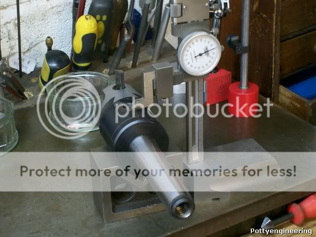
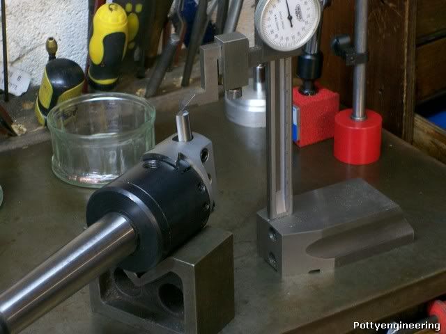
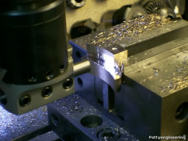
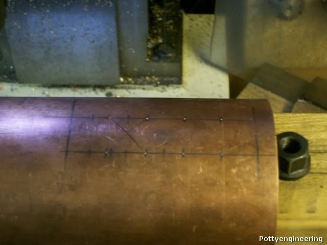
Then as its got to fit on the 3 1/2 " dia boiler tube, set up the boring head to cut that dia. The body of the head is 50 mm so (88.9 - 50) / 2 = 19.5 thats what the tool has to stand out above the body to cut a 3 1/2 " dia.

100_3842.jpg


100_3843.jpg


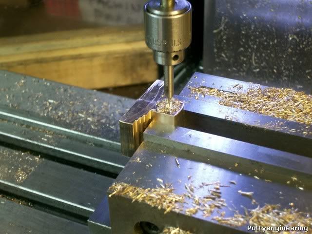
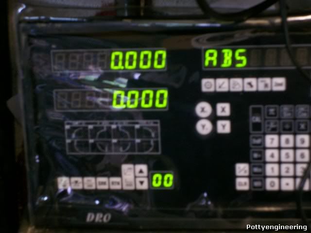
With that set, pop the job in the vice, centre drill for the 1/4*32 zero up the DRO swap to the boring head and cut the rad.

100_3852.jpg


100_3856.jpg


100_3858.jpg


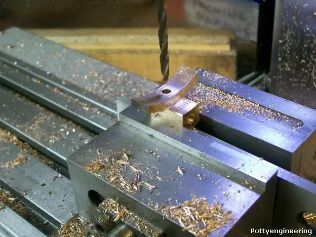
Then back to the zero position and drill for the thread.

Flip it round and drill the joining hole.

100_3861.jpg


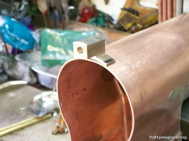
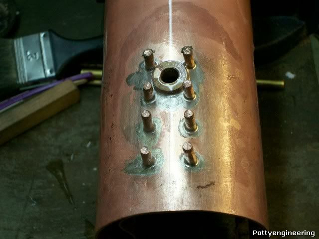
A clean up with a file and this is it on the boiler tube.

100_3871.jpg


Stew


Wonderful thread Stew.
I really appreciate all the helpful tips and techniques.
 
Thanks Zee

Showed the boiler to the inspector today big thumbs up . ;D

Stew
 
Got a little bit more done today, cut the fire hole in the firebox back plate for the, just making it a nice fit just a little bit of movement from the fire hole ring.

100_3872.jpg


Then soldered the ring in place, and while I was at it I solder some of the bushes in the backhead.

100_3873.jpg


100_3874.jpg


Thats a little more done.

Stew
 
Stew,

I have been quietly following along and this is going to be a really nice boiler. :bow: :bow:

A boiler is on my list but first I must finish the hit and miss. ::)

Best Regards
Bob

 
Thanks Bob.

Things bin a bit slow as we had a short holiday in London.

The guys at the club and the boiler inspector advised me to use crown rivet stays as they are far easyer to put in and just as effective, as the girder stays specified in the drawing. I couldn't get any rivets long enough so decided to make some out of 3/16 copper rod, I made a little upsetting jig this is simply a 3/16 hole in a chunk of steel, split through so that the rivet can be removed. To make the rivets I cut some 40mm length of copper bar, annealed them then put one in the jig with a short length protruding grip it tight in the vice and give it a good wallop with a hammer to upset the head. You can get the idea from the pic.

100_3875.jpg


Another bit of advice was not to try drilling rivet hole through both plates at the same time as the drill just wonders and the stays end up crooked, best to carfully mark the two parts out and drill them separately, this is the boiler tube marked out.

100_3886.jpg


And the set up to hold the boiler on the mill table for drilling.

100_3884.jpg


Drilling the stay holes, and safety valve hole

100_3889.jpg


Drilling the hole for the steam dome.

100_3888.jpg


for some reason the steam dome hole was going off line so finished the job off with a file.

100_3892.jpg


Steam dome bush fitted.

100_3895.jpg


Steam dome bush soldered to the boiler.

100_3904.jpg


Drilling the stay holes in the firebox.

100_3891.jpg


And a trial fitting of the parts the stays are not fully assembled in place.

100_3897.jpg


John was coming over this afternoon to help solder the stays but it was raining so we,ve put it off until Thursday.

Cheers

Stew
 
That's good going Stew Thm:

This looks to be quite a complex boiler! I did a bit of digging on the 'net, and found it is! :bow: - Great job!

Kind regards, Arnold
 
Stew

I am sure you know this but do not cut the stays off until you have SS the stays and pressure tested the boiler , they are needed to transfer the heat to the stay when soldering


Stuart
 
Thanks Guys

Stuart as you said I will leave the stays long as they help conduct heat into the silver solder joint, but I never thought of leaving them long until after the pressure test, as it will make any rework required easyer, good tip thank you.

Stew

 
Stew

I assumed you knew about the stays , but as we are all aware these topics are read by others and as such postings may help others

I note you have done the dome bush a belated tip jig the bush into the correct position level both ways then scribe round were it meets the boiler shell then drill four 1/16 holes just above the line at the points of the compass insert four copper rivets and balance the bush on these on top of the tube and SS, keeps it level


its your pressure tests not the inspectors that I mean when doing the stays

Stuart
 
Hi Stew
Thanks for taking the time to post this ongoing series. Looks really good so far.
Thanks again
Ferd
 
lordedmond said:
Stew

I note you have done the dome bush a belated tip jig the bush into the correct position level both ways then scribe round were it meets the boiler shell then drill four 1/16 holes just above the line at the points of the compass insert four copper rivets and balance the bush on these on top of the tube and SS, keeps it level

its your pressure tests not the inspectors that I mean when doing the stays

Stuart

Thanks Stuart I scratched my head about getting the done bush level in the end I resorted to rack of eye, but that's a real good tip for the future or any one else doing building a boiler, hopefully my eyes were in good form.

I was thinking when I've watched boilers being tested the stays have always been cut off, I just put it down to a different custom and practice at another club. For my test I was going to use a bicycle pump to put some pressure in the boiler and dunk it in the bath, if thats Ok, I was going to couple it up to my boiler feed pump and take it up to working pressure, if that OK then it will be over to the inspector. What routine have you used ?.

Thanks for your interest Ferd, I noticed this is your first post so welcome.

Cheers

Stew

 
well as I have sated before , use your pressure gauge and check the mains water press. it should be about 80 psi , then use that for first test.

then I use a loco hand pump to twice the WP in your case I bet its 80 psi wp then 160psi test.
just make up the hand pump early

under NO account pressurise the boiler with water and leave it to sit outside on a sunny/warm day. The sun is plenty hot enough to expand the water and put the press. us to very high levels . These pressures will/have over pressurised a new boiler to destruction ( no safety valves fitted for testing you are the safety valve )

Stuart


Ps got the non platform side valve gear fitted up yesterday now to make a scale wakefield lubricator about 1 x 3/4 x3/4 with a scotch bridle pump inside ( double O ring adjustable )
 
Stew

This may be unconventional but take a look at this option (scroll down) http://www.homemodelenginemachinist.com/index.php?topic=8687.msg95234#msg95234. These pumps are now cheapish ($15 on ebay) have a pressure gauge that go up to 300psi and the schrader valve thread is 5/16 x 32 so with a simple adaptor can go straight on the safety valve bush. It also allows you to bring the pressure up and down on steps so you progressively work harden the boiler that has been annealed through soldering. . Note: This is about using the pump with water in a boiler completely filled with water not air

Of course if your mains pressure is 80psi its an easier option but that can't do the 200psi you'll need to eventually test to.

Pete

 
Pete as Stew as not told us to the WP of the boiler we can only assume the test pressure its an LBSC ( Curly )so I assumed it to be 80 in keeping with his/her designs


it is first test to twice the WP and thereafter 1.5 time WP


my boiler is designed to work at 100psi therefore the initial test was 200 psi see my avatar
 
The working pressure is 80 psi so the inspector will test it at 160 psi.

The rain kept off today so manages to get the crown stays done.

The parts were given a good clean and the rivets assembled as the rivet passed through the water space I threaded a ring of easy flow solder onto it, the parts were then fluxed and another ring of solder added to the outside of the boiler tube that way the solder between the plate fed the joint with the fire box and the outside solder fed the boiler tube: so that we did the outside and the inside at the same heating.

The boiler was placed on the hearth firebox down, and with a large torch in the firebox and one smaller torch on the end of the rivet, on a roving mission, the solder soon melted all looked good, so after 1/2 hr in the pickle this is what we got.

Inside

100_3916.jpg


Outside

100_3922.jpg


In between

100_3926.jpg


All the joints had a nice fillet of solder :D

Before I do some more I need to get a few more rods of solder.

The next job will be the throat plate stays and the side stays:- 54 in total.

Cheers

Stew
 
You are having to much fun with this.

keep up the steady progress as has been mentioned by others the heating now will get harder


Stuart
 
Back
Top