Making a Boiler for a 3 1/2" Gauge Locomotive

Home Model Engine Machinist Forum

Help Support Home Model Engine Machinist Forum:

This site may earn a commission from merchant affiliate links, including eBay, Amazon, and others.
Thanks Arnold

Well yesterday was yet another case of "best laid skeams of mice and men all gang away". I could see the whole day in front of me in the shop, but I'd forgotten about the Boss, we'd booked seats for a Don McClane (of American Pie Fame) In Liverpool for the evening, but the Boss thought it would be a good idea to go early and have a wander around the shops visit the Tate modern art Gallery at the Albert Docks etc etc so strike one afternoon in the shop. Enjoyed the visit and concert though, and came across one interesting fact you guys across the pond will be interested in, theirs a very nice bronze statue at Albert Dock commemorating emigration donated to the city by the Mormon Church, it's plaque states that over 9 Million people emigrated from Europe to North America through the port of Liverpool:- just what % of the population are decended from those emigrants now :scratch: the mind boggles.

Back on topic:-

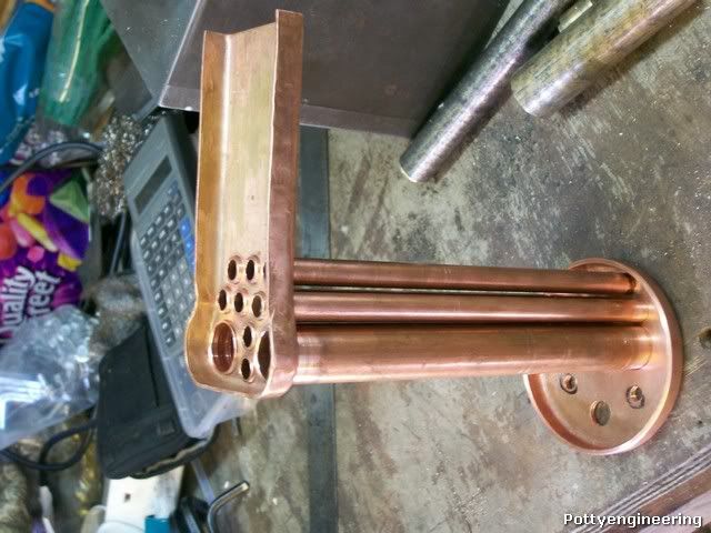
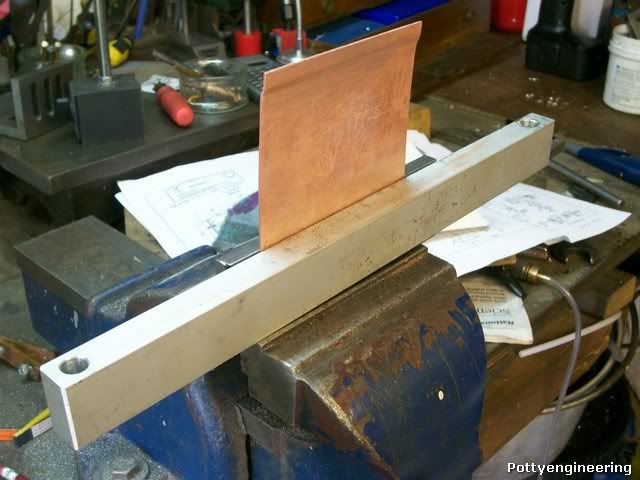
The wings of the fire box rapper need to be extended to do this I will have to make a joint, this can be a simple lap joint but this will take up some water space or a joggled joint, I'm going to use a joggle joint. First thing make a joggling tool, now this isn't going to be a fancy tool just dog rough and functional.

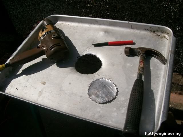
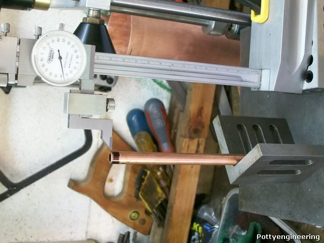
Mill a bit of flat steel (garage door thanks Ralph) flat and put a groove up it 1/4" + plate thickness + a bit for luck.

100_3751.jpg


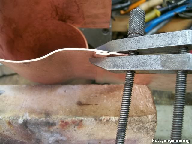
Then with the plate well annealed and a 1/4" square bar squeeze the plate into the grooves.

100_3754.jpg


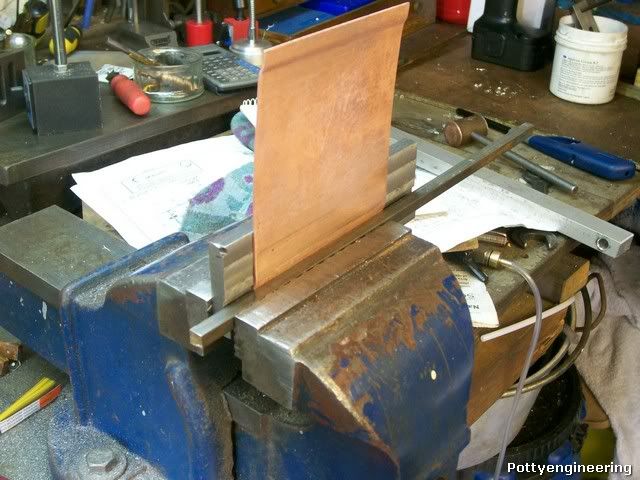
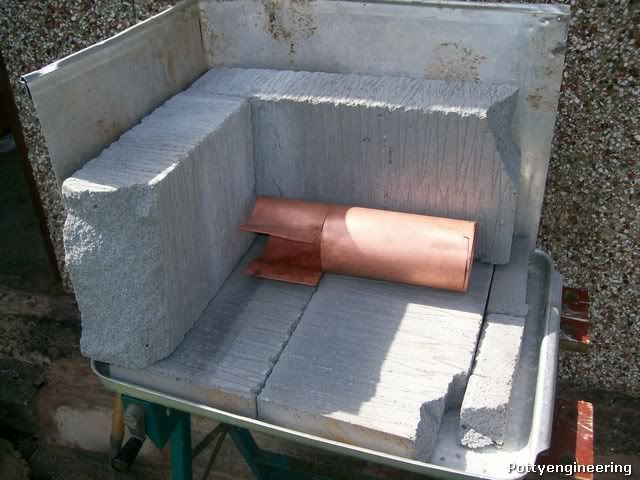
This will bend it out a bit wack it back square with a bit of ally bar and a hammer.

100_3755.jpg


And thats the joggled joint formed.

100_3757.jpg


Cheers

Stew
 
Coming along well Stew.

What did you think of Don McLean? I saw him live years ago and was rather disappointed. However, the venue might have had a lot to do with the quality of the performance.
 
Thanks Tel

This was the second time we've seen him, the first time it was very good, this time not so good, some how this performance wasn't as polished, both times were at the same venue Liverpool Phili Hall, so guess it was just an off day.

Stew
 
will it still fit between the frames with that joint ?

have you done the required calcs for the design alteration for that type of joint , better run it past the inspectors just in case

Thats why they fit a internal butt strap

its bad enough to get the stays down to fit

although yours looks OK but for others looking in not all copper pipe supplied is of a uniform wall thickness and can in some cases fall below the min section required for the SWP of the boiler , its worth checking
 
Hi Lordemund

Thanks for the input

The joint actually fits above the frame, I've tried it in the frame and its ok in fact it would fit between the frame.

In the instruction Curly gives both options of joint for the boiler, the boiler inspector said he preferred joggled joints, but I need to ask him about stay position.


Tube thickness is certainly worth checking I'll do that tomorrow, I've had that sort of problem with tube when I was working in industry.

Now if you've got a nervous disposition look away now:- this is going to be cheap, nasty, and as rough as the proverbial Bears back side.

(If any of you guys have felt a Bears back side and lived to tell the tail I would love to know just how rough it is) ;D

But It'll do the job

Making the brazing Hearth.

Fist off cut a boiler size hole in the base of a large ally oven tray:- the reason for the hole will become apparent next weekish.

100_3759.jpg


Then four bolts in each corner fastens it to the top of a work mate, and a bit of scrap ally sheet pop riveted to two sides makes the wind shield.


100_3761.jpg


Now it was a great bit of advice that I got to use Thermalite block cut in half with an old saw for insulation. (You must keep them dry)
They cut like butter.

100_3762.jpg


And her we have it's all ready for the first soldering job and all for less than a ten squid, and build in an afternoon.

100_3764.jpg


Stew


If the boiler inspector is Ok then it will be fine

I am not trying to be a doom merchant but you cannot be to careful with pressure vessels just think where it will be placed when you drive the loco :eek:


but I am trying to stop you making a very expensive mistake you need to be about twenty steps ahead its all to easy with boilers to forge ahead and cause you problems in the future


I cannot remember if LBSC included blow down valves , but do a quick count up of the number of bushes required for clacks, water gauges and manifolds

as a after thought think how you will fit the fire door and catch and provide a small tapped blind bush in the required positions


Stuart
 
Hi Stuart

I really appreciate your input I'm very much outside my comfort zone with the boiler build, most of my training was in machine shops, so once I step outside that I start to struggle. I can understand what you mean about forging ahead and causing an expensive mistake. I'm a little uncomfortable with how the throat plate fits to the boiler tube old Curly just says cut the tube half way across, once I done it and tried the throat plate I would have bean happier to have only cut 1/3 of the way, still I've done it know. One of the first things to solder will be the throat plate I just hope the inspector approves it.

The drawing does call for a blow down valve at the front left of the fire box, I was planning on soldering it in place at the same time as I do the foundation ring.

There are two different drawings for the Back head, that show different bushing arrangements Curley's drawing and one in Matin Evan's article on finishing the loco off, after he took over when Curley passed away. I've gone with Martin Evan's drawing as it meets the boiler fittings requirements logically. Two clacks, two water gauge, one regulator, one blow down valve, two stays, as well as bushing in the tube for a manifold.

With the fire hole door I'm still confused, Curley shows the backhead plate drilled and tapped for the door, but above the fire hole, I can't see how the door fixes ?, Martin Evans doesn't show any thing, I was going to have a read in shop and shed and have a word with the guys at the club how to do it.

Thanks again

Stew

 
where he shows the backplate drilled for the door and catch, just drill the holes now and SS in small blind bushes tapped for the screws to hold on the hinge and catch

The best way is to side hang the door that way it will stay open when firing on the move

 
Stew

On this joggled joint; it occurred to me why not rivet the joint as well as SS it? The rivets will make it stronger and serve keep it all in place during soldering process. I would assume there's a whole lot of stay ends in this area as well so the rivets wouldn't be that out of place.

Pete
 
Pete

I'm going to use rivets as you suggested, my plan was to start soldering yesterday the first job was to be the fire box extensions, I thought I had some 1/16 copper rivets but discovered they were steel :mad: , so I'm waiting for the copper ones to be delivered, in the mean time I've started machining up the bushes for the boiler.

Cheers

Stew
 
Stew

On the bushes do make the mistake I did and do them in brass and then have to do them again. I only discovered my mistake when one melted due to the over exuberant application of heat.

No doubt to somebody with your skills you'll have them all knocked out before morning tea break.

Pete
 
Thanks for the warning Pete

I,m making the bushes from Phos Bronze, I don't know about getting them done before tea, started on the bush for the steam dome, its got 12 holes on a pitch circle dia first attempt I got the PCD wrong I had to remake, so all I got to show for yesterday was that one, and a start on the stay bushes.

Stew
 
Got some of the boiler bushes made whilst waiting for the rivets to arrive.

100_3765.jpg


The bush on the left is for the safety valve, the drawing states 3/8"*26 thread, checked with Reeves what thread they sold their safety valves with 3/8*32 so thats what I made it, the middle two are for the regulator they screw into the end plates, the one with all the holes is soldered into the boiler barrel and the steam dome fastens onto it.

Stew
 
Good going Stew Thm: - very nice parts!

Do you have taps and dies for all those unique (to me anyway) threads or do you single-point them?

Kind regards, Arnold
 
Thanks Arnold

My lathe is very unfriendly when it comes to screw cutting so I use tap and dies where I can, I've slowly put together quite a comprehensive set of ME taps and dies over the years, buying them when needed, bought 3/8 * 32, 3/8 * 40, 7/16 * 32 and 7/16 * 40 at the Harrogate show the other week. Some tome ago I bought some real cheap carbon steel tap and dies made in India they were real poor quality:- the taps chipped and the dies didn't cut a clean thread, since then I've only bought HSS or Carbon steel stuff made in the UK. ME thread sizes tend to be used mainly on brass parts so good quality carbon works just fine.

Cheers

Stew
 
Arnold,

I didn't want to take the wind out of Stews sails, but in the UK we have some standards that are normally used, and they are ME threads. That stands for Model Engineering, and when you order commercial fittings, they are usually cut with one of those, unlike on the continent, which usually uses metric.

These are standard ME threads, 40 & 32 TPI, but some coarse ones also come as 26 TPI. Have a look at taps/dies in wooden boxes.

http://www.tap-die.com/index1.html

I am just saving up to buy myself a full new set of taps and dies of most British normal threads. I have BSF & BSW arriving tomorrow, and worth every penny I paid for them.

Tap & die have special offers on at the moment, so I am going to take advantage of it, as I have found their taps and dies are second to none, especially on stainless.


Bogs

 
Stew, Bogs - thank you both.

I was wondering, as for steam the finer threads seems to be a better solution than the normal metric I've used so far... My bad as well; I didn't check the ME size charts :-[ - I always forget that one as I've never worked with it.

Stew - nothing wrong with using taps & dies for making threads - even if your lathe is up to it ;D - much easier if you don't need single point accuracy!

Bogs thanks; that link has me both envious and approaching cardiac arrest; The prices do look very good indeed - just a bit above my budget :eek:; though I'll admit the basic collection of metric taps & dies I have (good quality though) actually cost just as much to put together.

Kind regards, Arnold
 
Arnold,

Not so much in your metric empire, but one other advantage of the 40 tpi, that is what is used in an imperial micrometer, so you can easily make fine tune items with a thumbwheel graduated in thous, 0.025" per revolution.

Like Stew, I have used the cheaper carbon sets, because that is all I could afford at the time, but even though they cut well enough on non ferrous, not so with harder materials.
They are not used everyday like metric or BA (which I already have in HSS), so I have come to a time in my life where good quality sets should last me the rest of my natural. Anything to make life a little easier.

John
 
Thanks for the info John those tap-die prices look very good for the box sets top quality too.

This is where I get my Carbon stuff from http://www.tracytools.com/ the prices are for carbon but they do stock HSS they usually double the price up for the HSS stuff.

Avoid the unboxed sets they sometimes sell, these were the cheap Indian manufacture that were poor quality, rest of the stuff is OK though.

Stew

 
Well this has been a very frustrating week, I ordered the 1/16 copper rivets on Monday on Friday I got a call from the supplier to say they were out of stock :-\ , so I've reordered from another supplier, in the mean time I've got on with some house jobs and earned a few brownie points, and made some more bushes, and bronze screws to hold the boiler together whilst its soldered.

100_3790.jpg


I found that the boiler flue tubes varied in length by 1/8 they need to be all the same length or the sort ones will be at risk of coming adrift during soldering.

100_3776.jpg


Skimmed one end square de-burred the bore and skimmed the Dia for 3mm for a lose fit in the tube plate.

100_3773.jpg


Then found the shortest tube and set the hight gauge to that and marked all the other tubes off to that length.

100_3774.jpg


Skimmed the length to the mark and turned OD same as the other end.

With all the tubes trimmed to length and a small step turned time to have a trial assembly to the tube plates.

100_3779.jpg


100_3785.jpg


The smokebox tube plate is the wrong way round, this is because I want the end of tubes to sit flat on a plate whilst I solder the tubes to the firebox, the smokebox tube plate will be one of the last things to be soldered so I must remember to turn it round.

My plan is to solder the wrapper extensions first then the throat plate and wrapper, but I need those darn rivets if I don't get them soon it will be plan B turn some 1/8 rivets down.

Stew

 
Back
Top