Making a Boiler for a 3 1/2" Gauge Locomotive

Home Model Engine Machinist Forum

Help Support Home Model Engine Machinist Forum:

This site may earn a commission from merchant affiliate links, including eBay, Amazon, and others.
Thanks for the input Chaps we'll get this job cracked between us.

Picked up a nice bit of 2.5mm thick copper the drawing spec is for 13g 2.33mm so its on the safe side, while I was their they cut me a 2" lump of 15/8 phos bronze for the steam dome bush, and I also picked up a length of 1/8 phos bronze to make some closing screws, and a rod of Easy Flo No1 silver solder this has a slightly higher melting point than Easy Flo No2 that I'm going to use on the bulk of the boiler, but there are a couple of places that I want to use this higher melting point solder, as the joint will be subjected to high temperatures when I'm soldering additional joints close by.

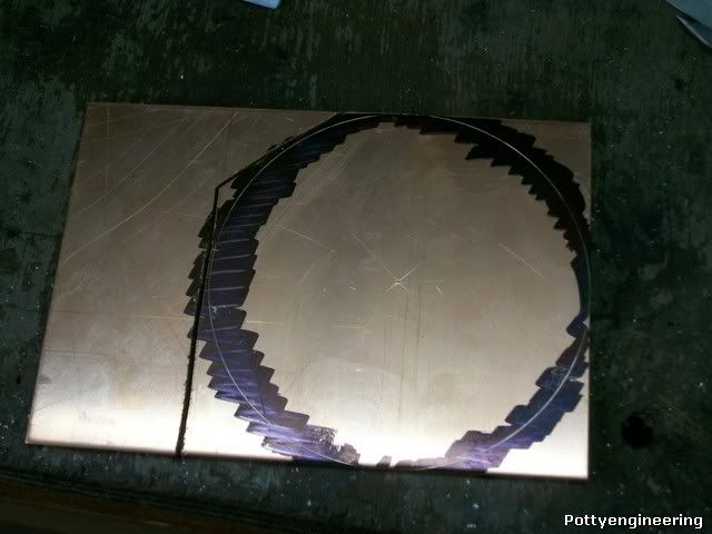
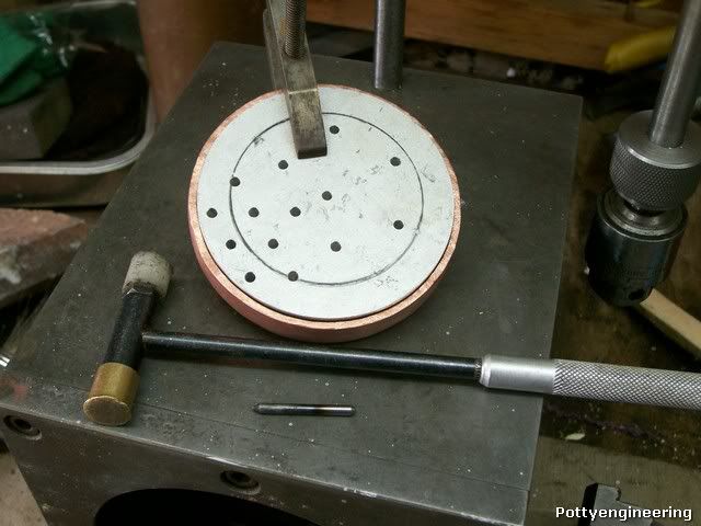
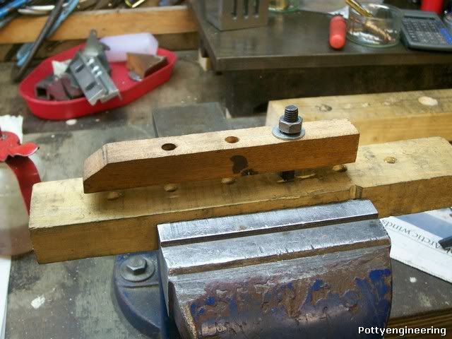
Work on the new fire box tube plate first job mark out a circle 3 7/8 dia (3 3/8 + 2 * 1/4) the 1/4 is so that the flange can be formed.

100_3613.jpg


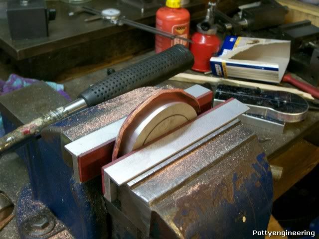
Then mark a 3 3/8 dia circle so the former can be centred, then anneal the plate, clamp the disc in the vice with the former and start to fold the flanges over with hammer blows, the copper starts to work harden quite quickly you can feel the material stiffen under the hammer don't try and force it or the copper will split, anneal the plate again.

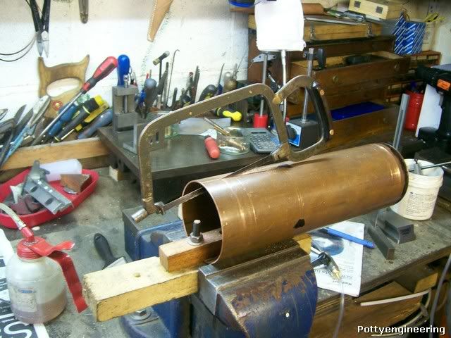
This is it after the second anneal.

100_3615.jpg


In total I annealed it 7 times before the flange had formed over onto the former.

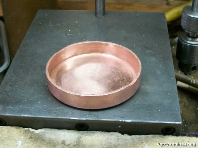
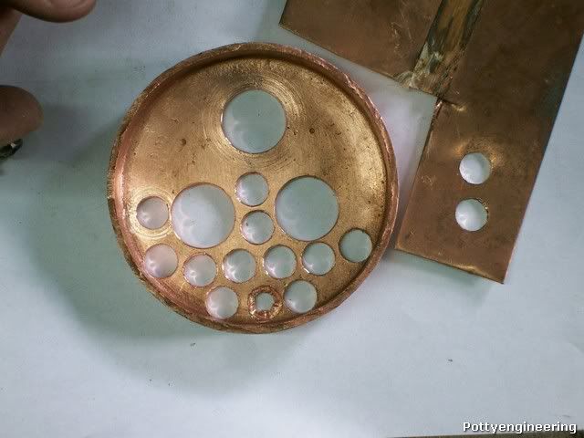
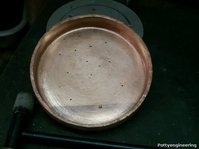
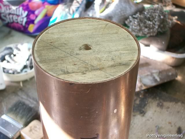
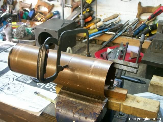
This is it complete after an hour in the pickle bath.

100_3635.jpg


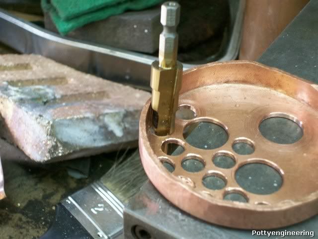
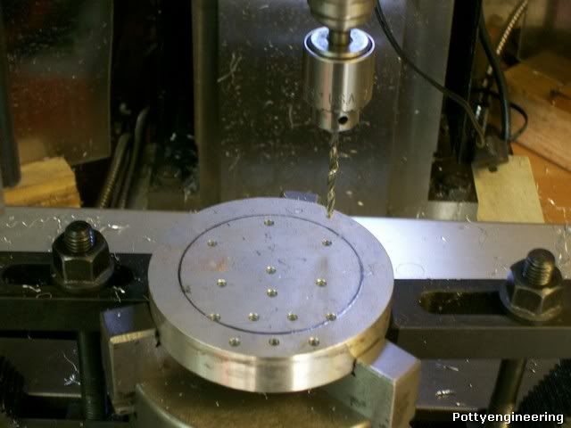
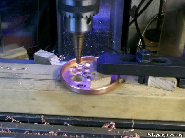
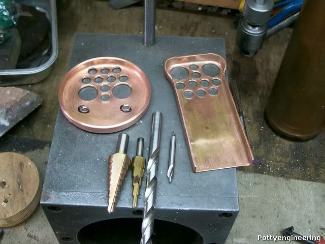
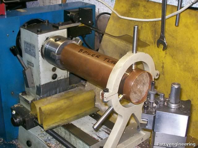
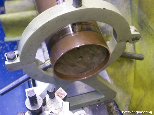
Well that me back where I started before I try drilling the plate again I'm going to have a bit of an experiment and make some kit that should make the job easyer.

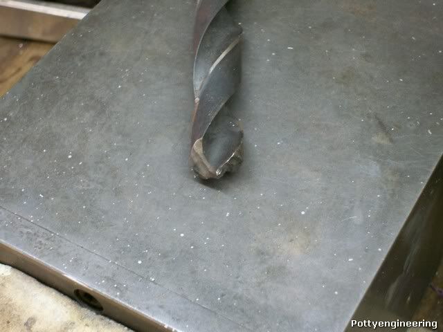
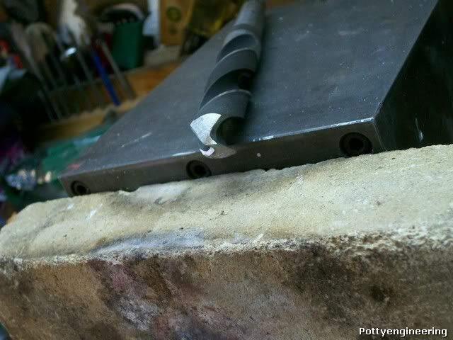
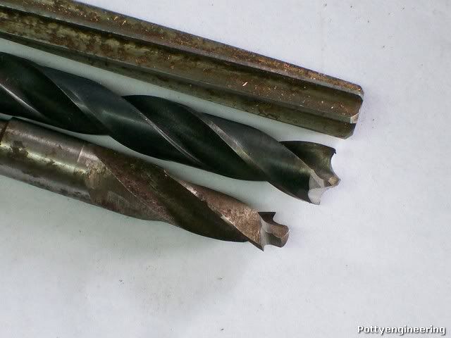
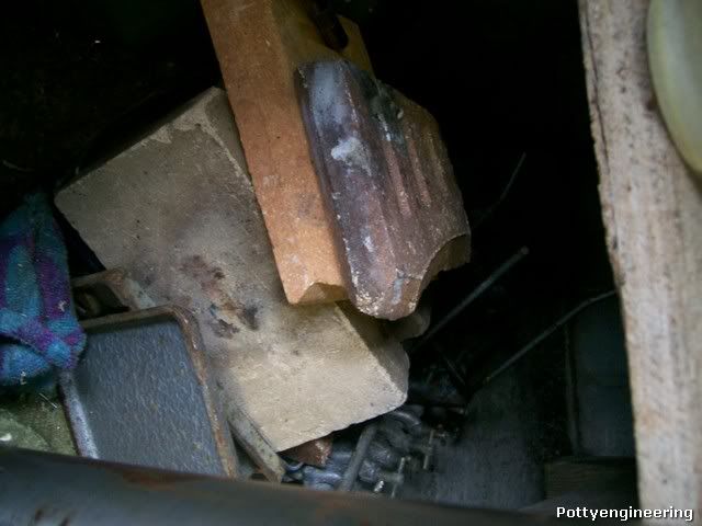
This is going to be a bit of topic:- I want to grind a drill up specifically for sheet metal whilst searching my drill stash for a spare 3/8 and 3/4 drills I came across this sorry site:-

100_3622.jpg


I must have picked it up out of the scrap where I use to work.

So I decided to give it some TLC, my Dad taught me how to grind drills up by hand when I was an apprentice many years ago, and like riding a bike its just something I can do, if you asked me to explain it I couldn't, I could show you but explain it no.

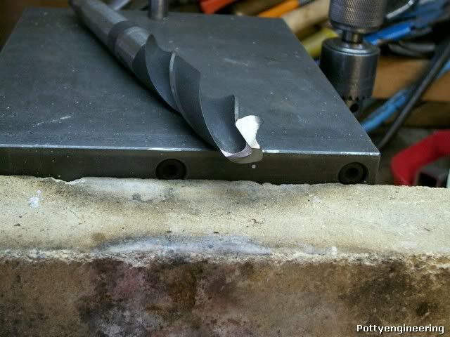
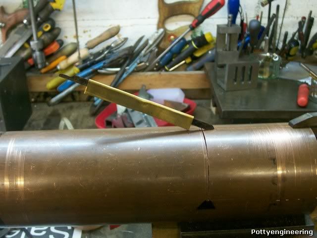
Any way this is the result.

100_3631.jpg


100_3632.jpg


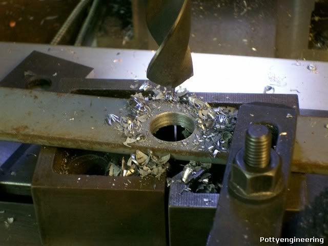
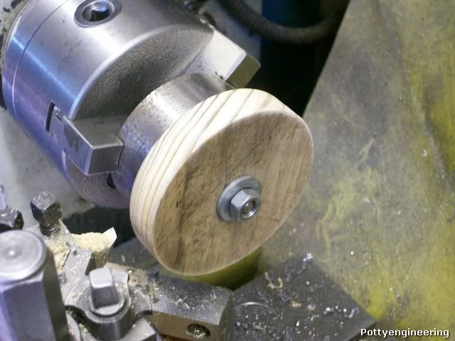
And the proof of the pudding.

100_3634.jpg


Still got the touch :D

Stew

 
Excellent flanging work, . . . and a better drill point than I could make.
 
Thanks Harry

Quick up date.

John has kindly given me a loan of some imperial step drills:- Thanks John

But I found a problem in using them three of the holes are right up against the flange and the drill will catch it.

100_3645.jpg


So I ground a 3/8 drill up as suggested by Rob but it cut too 0.020" over size but I found a 23/64 drill among my stash, most of these drill I inherited from my Dad and its a weard and wonderful collection, but don't knock it you can't beat weard . So I ground that up and it gave a hole that cleaned up nicely with a 3/8 hand reamer.

100_3659.jpg


Had a practice with the scrap tube plate, I used a drop of milk as a cutting fluid as suggested by John:- Semi skimmed worked ok

And this is the result.

100_3661.jpg


The bit of sheet is 0.5 mm thick

Top Job

I then drilled 3mm pilot holes in the former using the mill DRO this is the set up.

100_3669.jpg


And made a stubby centre pop out of a bit of 3mm silver steel (drill rod)

And marked the position of the holes in the new boiler tube.

100_3641.jpg


100_3642.jpg


I decided not to drill the tubes just yet as I wont to ask the boiler inspector a couple of questions, I'm a bit concerned with the closeness of some of the tubes to the flange, the drill will just kiss the flange, and I was wondering if a should slightly reposition these holes.

So I'll get on with something else.

Stew
 
don't forget to file your nicely drilled holes with a course rat tail file and to file a chamfer on each side . reason to give the SS room to flow though the joint ( you can only work from one side in some places ) the chamfer give a small filet space.

while I am on. when you do the stays on the outside counter sink the stay holes with a very blunt drill or use the drill in reverse . reason this will raise a small dam round the counter sink and retain the SS. try it on your test piece of copper first though

note you need about 5 thou clearance on all joint faces for the SS to wick in


BTW i you can get hold of the book by Alex Farmer it is a good read


Stuart
 
Very Nice project Stew. I will be watching with intrigue.

Is there a reason no one has mentioned using an end mill to finish the holes to size? I do this quite often on thin materials like 1/32" brass sheet, and get very good results. I have also made holes in thin walled cylinders of brass and steel using end mills.

Kel
 
Kel,
I can't speak for anyone else but for me it's expedience. To mill the holes the heads will have to be securely set up and aligned, just as if you were milling, which one would be. Also, unless you were using a center-cutting mill, pilot holes would need to be drilled. Nothing difficult about this but this does take additional time and I've found I get no better holes and job than if I use a step drill. With the step drill I just mark out the head, deeply center-pop, plop it on the drill press, and have at it.
 
Hi Stew;
Been watching this on both places, so, some questions here, some there.
When you banged up that last round plate, how do you keep it centered on the former as you turn it in the vise? Just eyeball it?

Thanks!

Dean
 
Dean

When I started with the square plate I lightly put a centre pop where the centre of the disc would be, I then marked out a circle 3 7/8 dia and cut this out by saw and filed to the line, I then lightly marked another circle the same diameter as the former in the middle of the disc, I then lined the former up on this and gripped the two in the vice, hammered over a good 1/3 of the plate, then by hand held the two together and undid the vice with the other hand and repositioned them, hammered over another 1/3:- repeat. Once I'd got this first bend complete the former self aligned for follow on hammering over operations after annealing.

Hope this helps

Stew
 
The first plates I made I fiddled about getting the copper cut nicely round and then centered on the former. I then realized this was all unnecessary. I now rough cut the copper sheet to near round, in a series of straight cuts (and have since found I can do this very quickly on my mechanical hacksaw). I then roughly center on the former and shape the annealed plates. When finished and still hard from the final beating I stick the plate in the 3 jaw chuck and skim off the excess. Its quicker in the long run. Of course this only works for round plates and if they are of a size you can get in your chuck, however even my little Lorch can do 3"plates.

boiler13.jpg


BTW - If the step drill can't be used from the flanged side can't a pilot hole be drilled and the plate just be turned over and drilled from the other side?

Pete
 
Thats a couple of good tips their Pete

Thanks

Stew
 
Stew

No problem. I'm looking forward to this build as well as everybody else. I know you said it was a kit boiler. Can you let us know which one just in case we have the drawings to allow us to follow.

Pete
 
Hi Pete

The boiler is for a 3 1/2" gauge Mabel to the design LBSC reading through the Model Engineer article Currly says that he used the same formers as for the boiler of "Jeanie Deans". The serial for the Loco build In Model Engineer ran from April 1966 to May 1968, it was the last Loco LBSC designed he passed away before the serial was was finished and Martin Evens went onto complete it.

Cheers

Stew
 
Thanks Stew

I've got LSBC's "Shop Shed and Road" and Martin Evans "Model Locomotive Boilers" and I'll take a look to see if there any reference to it. However, from what I've read most of their boilers tend follow a pretty common approach.

For example; I had been wondering why my safety valve didn't work so looked at all the information I had in various books, drawings, information from this site, examples of commercial valves etc and concluded that all those that worked semed to go back to the design Curly provided in "Shop Shed and Road" in 1929. (Off topic but one observation I did make in that assessment was that for all the valves that "worked" the ratio of the area of boiler side bore and the cross sectional area of the ball was 64%-69% which may or may not be relevant.)

Pete
 
Thanks for the good information Guys its information like this that can pull a job out of the mire. I've got an old copy of shop shed and road it's the must have book for loco building.

At the club night on Tuesday I took my scrap tube plate along more to get the Chaps talking and it really paid off, some of the old guys are have lots of experience building boilers, along with offers of help if I got stuck I got lots of advice and tips to get the job going.

Any way on with the tube plates:-

I clamped a chunk of wood to the mill table and drilled a hole though it to clear the drill and another for a clamp on the job.

This is the set up.

100_3699.jpg


To drill the holes I started them with a centre drill then for the 3/8 a 8mm cone drill and then a letter U drill the guys at the club recommend not reaming to size but to leave it slightly under size and turn a small step on the boiler tube, this way it will have something to sit against and not fall through when you start to solder.

I used the cone drill for the 3/4 as this was giving a hole that was under size on the tube again I'll take a fine skim off the tube.

Here they are finished.

100_3700.jpg


Next job skim the boiler tube square and too length.

So that the chuck won't damage the tube I turned up a wood plug a nice tight fit in the tube.

100_3691.jpg


100_3693.jpg


With one plug in the chuck end I couldn't get the tube running true at the steady end as the tube was oval so I turned a second plug up for that end as well, this pulled the ovality out of the tube.

This is the set up

100_3695.jpg


100_3696.jpg


I just could,t have done this with the 3 point steady as it was.

Cheers

Stew


Stew

It's looking good mate. You realise you are centre stage now so you have to keep going 'till it's done. Amongst the others I'm keen to see how you go as I'd like to do one of these one day.

Pete
 
Thanks Pete

Things have slowed down a bit on the boiler build I've got a paying job that will take up some of my time for the next couple of week.

Got a bit done drilled the holes in the Backhead sorry no pics and made a start on the boiler tube.

Marking it out used the mill table as a flat face.

100_3713.jpg


In order to hold the tube steady for cutting I used this clamp I made it a few years back for another job:- can't remember what :scratch:
Just two pieces of wood with a coach bolt.

100_3714.jpg


This is it in use

100_3718.jpg


I used a junior hacksaw to do the business, this one has a sentimental attachment for me my father made it many years ago, I didn't want to use a 12" saw as the tooth space would be too wide for the tube and tend to rip also I wanted to take it steady so I got a nice clean straight cut. As the saw was cutting at an angle I didn't take it past the line I left a bit of metal holding the tube together whilst I did the next cut.

This is the next cut, the tool makers clamp is to to stop the cut ends from vibrating and making a farting noise.

100_3720.jpg


The with a junior blade held in a bit of brass chim complete the cuts square.

100_3721.jpg


This is the cut tube.

100_3730.jpg


The cut will be bent out to form the wings of the firebox, I tried to bend them out as cut but the copper is quite hard so I'll anneal it as I didn't want to force it. As the annealed tube will need pickling I,m at a bit of a stop until I get my pickle bathe made.

I've collected one a two things together for the boiler build.

100_3733.jpg


The black box is a case from an industrial battery fork lift truck or something like that, and will be part of the pickle bath, the bits of ally behind it will form part of my brazing hearth. At the Harrogate show I picked up some of these blankets, for the hearth.

100_3736.jpg


I also have a collection of fire bricks.

100_3737.jpg


Getting there slowly

Stew


Stew

Its looking good; and I know what you mean about paying jobs I'm between numbers myself at the mo' so have a bit of time on my hands.

With that battery box what do you plan to use for the pickle? Citric acid from the baking shelf at the supermarket works fine and is safe. Three $2 pots in a plastic storage bin half full of water worked fine for me. I dunked my bare hands in it to fish stuff out. It did sting a bit if I had cuts in my hands but under the tap and problem solved.

And for the hearth just get some Thermalite/Celcon blocks from B&Q and cut them up with an old rip saw. Those firebricks absorb too much heat. I had soldering issues but once I went to Autoclaved Aerated Concrete (AAC) block my problems went away as the heat was then going where I wanted it.

Good luck

Pete

 
I will second the thermalite bricks boy do they reflect the heat just keep them dry :)

as I have posted on your other thread do not make the holes to good a rub with a rats tail file and a chamfer on both sides will allow the SS to flow into the joint


Back
Top