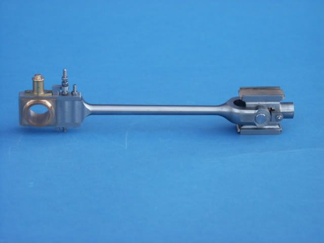
MainRod with adjustable brass's

Home Model Engine Machinist Forum

Help Support Home Model Engine Machinist Forum:

This site may earn a commission from merchant affiliate links, including eBay, Amazon, and others.

johnnyo

Well-Known Member
Joined
Jul 22, 2012
Messages
68
Reaction score
63
Hello
I wanted something different for my A3 build so initially it was a duplex steam pump and now it seems I wanted a more intricate rod. I may get this engine built by retirement or i'll be assembling all the pieces I've made over my lifetime at retirement, whatever. I was forwarded these plans via a picture that I used to piece together a drawing on drftsight. It turned out rather nicely so here it is. IMG_1697.jpg

IMG_1669.jpg
 
Nicely done Johnnyo. I've been pondering how to make the slots since those that I've seen had squared off ends.

Yours appear rounded. Are the cotter and drift pins rounded also to bed into the slot ends?

Phil
 
Phil
Yes, they are rounded and the small round tower on top is for lubrication.
JohnnyO
 
I would be very worried about using that design of bearing retention. As it stands when the rod is in tension all the load is being taken by the small adjusting thread on the wedge.

Its is usual practice to have a strap retained buy fitted bolts/studs around the outside and the wedge and the cotter on the opposite side of the bearing so they are in compression not tension. Take this one as an example there are two bolts so 4 times the area to take the loads

PICT0109.jpg


I would also say that the wedge is the wrong way round. It should tighten the bearing as the nut is tightened, on yours there is no means of tightening the wedges save for tapping the cotter in and out.

J
 
JasonB
You got me on the ropes man, but now I'm coming off. The design I used is the one P.R.R. used, if I remember my homework. Taken from an image in one of the railroad encyclopedias. I had an image of you're design shown as well but chose this one because it interested me more. The wedge Adj. bolt you speak of is actually the hold down bolt pulling the flat nail head of wedge down against top of rod. The tapered Key is driven down thru key block to react against key bolt and push brasses together. In real life the key is locked in position with two square head bolts, I used two set screws there instead. All tension force goes straight back to rod straps, I'm confident it will hold up to model stress as well as prototype. Nice rod you made there, what is it for?
Thanks
JohnnyO
 
jasonb

Beautiful tractor, what size is this and what is the dome between the front wheels on these tractors for? Very nice work, hope she runs a nice as she looks.;D
JohnnyO
 
2" scale so about 36" long

The spud pan was not often used for carrying the spuds(extra cleats for the rear wheels) but used more for general storage.

J
 
Back
Top