Machining the Webster piston (lots of pictures)

Home Model Engine Machinist Forum

Help Support Home Model Engine Machinist Forum:

This site may earn a commission from merchant affiliate links, including eBay, Amazon, and others.

deere_x475guy

Well-Known Member
Joined
Oct 26, 2007
Messages
900
Reaction score
13
Location
Eaton Rapids MI


I have been putting off making the piston until I purchased a brake cylinder hone. Today I visited the local auto parts store in hopes to find one small enough. The bore is .875 and although they had a 3 stone hone that said it went to .844 it wouldn't fit, so it was a good thing I took my cylinder with me. They did have a 2 stone hone that fit and it worked just fine.

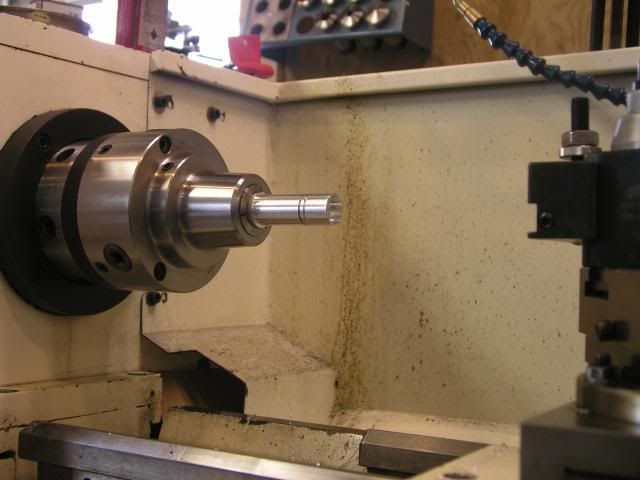
After honing the cylinder it was time to make the piston. I started with a piece of 1” 6061 rod held in a collet. Final diameter was targeted to be .874. The very last picture will show I ended up .00015 over. Next I cut my ring groves .59 wide to a diameter of .771. The plans called for .094 wide rings but after talking with Otto Engine Works he advised to go with a narrower ring to reduce friction. The plans also talk about doing this. He changes $5.00 each to grind the rings down but also said if I had a surface grinder it would be easy to do myself, so that's the plan. Once the ring groves were machined I center drilled the end, drilled .5 deep by .375 diam. This gave me a start to bore .250 deep by .075diam at the piston skirt.
P1010413.jpg


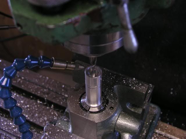
Now it's off to the mill to ream the piston pin hole and mill a slot for the piston rod. Here I am using my wiggler to find the center of the cylinder. I touched off both sides and divided the results in half (well actually the DRO did the math).
P1010415.jpg


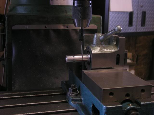
I also had to find the end so that I could drill and bore the piston pin in the correct place. The end of the wiggler is .100 so I have to remember to move the table another .050 before I zero the DRO.
P1010416.jpg


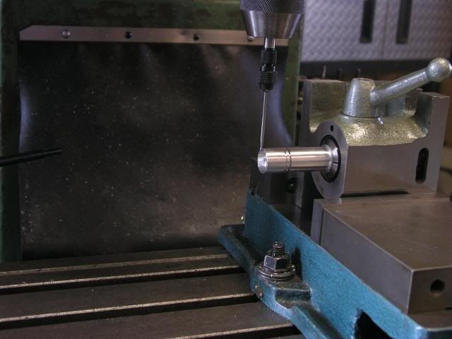
Here you can just make out the reamed .1875 hole.
P1010417.jpg


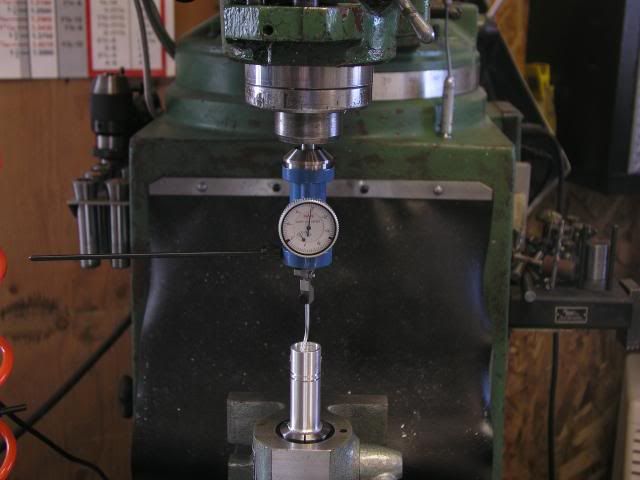
Next was to mill the .375 slot to make room for the piston rod. I used this style indicator to quickly find the center of the piston. It works really great. You start out by getting the part close to center (turn the spindle by hand holding onto the indicator, move the table axis until you have very little movement in the needle). Once I am with in a couple of thou I turn the mill on, (rpm=120) hold the black rod you see sticking out to the left then move the x-y axis until I no longer see movement…or very little. I quit fiddling with it when I was below. 0005.
P1010418.jpg


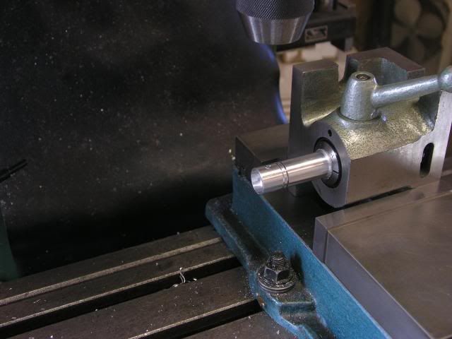
The plans call for the slot to be .750 deep, so I touched the end mill off the edge of the skirt to find 0. Then I moved to the center of the piston and plunged down to .750 with a .375 end mill (remember that I had already bored a hole on the lathe .5 deep so I was really only plunging .25). Now to finish the slot to length (.688) I needed to move my y axis .1565 to both sides of zero and the slot was done (slot length .688 -.375 =.313. 313/2=.1565). I didn't use any coolant but did run air in the slot to clear the chips since I was removing so much material in one step.
P1010419.jpg


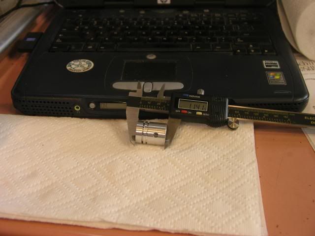
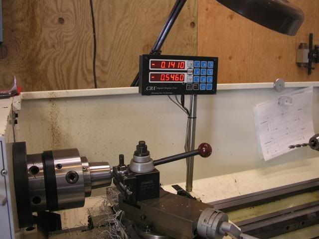
After cutting the piston off with the band saw I placed the piston back on the lathe and took a face cut. Then removed the piston and measured to see how much more needed to be removed for a final length of 1.0. Here you can see that I need to take .141 off.
P1010420.jpg


Once the piston is back on the lathe I touch the tool off the end and zero the DRO.
P1010422.jpg


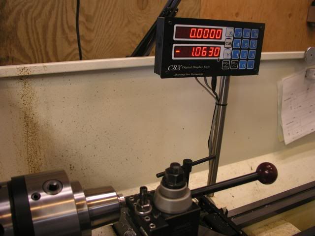
Cutting to length this way takes and extra step but the results are worth it.
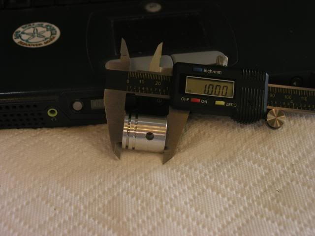
P1010423.jpg


Awh…a perfect 1.0
P1010425.jpg


Right now I have a nice sliding fit. With everything together if I hold my finger over the spark plug hole the piston takes 12 seconds to move 1.5 inches. This is measured dry! Not sure how long it would take if I have a slight film of oil on the cylinder. It may just not be enough clearance. I guess I will find out when I run it.
P1010426.jpg


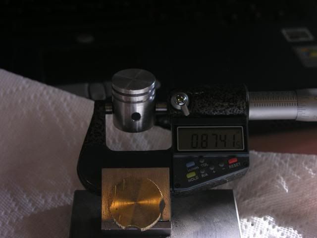
Here is what the piston measured.
P1010427.jpg


I hope I didn't ramble on to much and that everything made sense. If I lost anybody along the way just shout and I will try to clear things up.

Cya gang....next up is the piston rod.
 
Great show!!! I use those collets a bunch in my home shop. I have a collet chuck for my small lathe and a set ofcollet blocks. That takes care of most of the stuff I do. A collet fixture like you use would be handy sometimes though. Thanks for the step by step.

Wes
 
Nice step by step procedure. Excellent looking piston. Looking forward to the whole complete engine when done. You do nice work.

Bernd
 
Thanks everyone!

Wes, I love the collets, I am scouting and er collet set right now. Do you or anyone else know of a set with a 3/4" holder. This way I could use it in the lathe and mill.
 
Love the build pix! Makes me want to make a backplate for my collet chuck.

Bison make ER16, ER20, and ER25 collet chucks with a 3/4" shank. I mention Bison first because their collet chucks are particularly nice.

If you want ER32, Bison hasn't got it in 3/4". I did a little sniffing around and found a 20mm shank on eBay. Item #120221338274 from ctctoolseller. Seems to me it would not be a very big event to turn that shank down the 37 thousands or so it needs to be 3/4". It's pretty cheap, too.

Cheers,

BW
 
Hi DeereGuy! I don't know if you've honed your cylinders yet, I may be too late with this tidbit, but have you considered lapping? I've tried honing several times, and maybe it is my technique, but I always ended up with an excessively belled bore. I felt like I had little control. Then I discovered cylindical laps, and haven't gone back! They give a terrific control over every aspect of creating a good bore. The radial engine in my avatar had its bores lapped, and I was able to create 12 cylinders all to 1.0003", +.0002, -.0002, as measured with a good 3-point bore mike. I'm not saying this to toot my horn, it simply demonstrates how easy lapping is, in my opinion, vs honing. You can then, if you desire, create a tapered bore with ease. I did not, and simply left them cylindrical.

cyl03.jpg


Anyway, however you did it, the piston looks great, as do all your other components. Thank you for sharing this excellent build.
 
I meant to add this, but forgot... the fit of piston to bore is pretty critical. It sounds like you have an excellent, close fit, but remember that aluminum expands differently under heat than steel, and if there isn't adequate clearance, the engine can seize, with disastrous results. It is the piston rings that do the sealing in an IC engine rather than the pistons. If you are executing the engine to print, and are getting the dimensions called for, then I assume all will go well.
 
Swede, thank you very much for both the tip and the compliment. The total clearance as best I can measure is .0015 to .002. The prints call for a .875 lapped bore. I have honed many wheel cylinders back in the day when you actually repaired things rather than throw them out. I found the trick is to keep the hone constantly moving back and forth in the bore, never allow it to sit in one spot. Also I will switch ends when I withdraw the hone to check for fit and start it on the other end. I know that learning the proper way to lap is probably the best way to go and my hats off to you. Your engine is very impressive looking. Have you considered posting more pics of it. I have and Edwards Radial 5 that I started the cam on and haven't gone any farther yet. Not sure when I will get back to it because I have already picked out the Rotary Valve steam engine (plans posted here) to be my next go...

This weekend is pretty much lost (engine build wise) because I am switching the DRO out on my lathe and figure it will be most of the weekend setting up and learing how to use the new one.

PS have you also considered posting your lapping technique? I for one would love to see it.
 
Hi Bob, your piston to cylinder interface sounds fine. It's funny, nitpicky home shop machinist types don't like sloppy fits. We tend to make tighter fits when not only is it uncalled for, it can be downright disastrous. Piston to bore, and valve stem to valve guide are two big ones.

Obviously your experience with honing has served you well. I tried a number of brake hones, and for me at least, it was a disaster. I know that there are some quality honing tools out there, such as Sunnen, which might help a new guy. As for lapping, the technique is to find a lap that is preferably longer than the bore, but that is not critical. The cylinder is bored in the lathe as best you can, leaving behind perhaps 0.001" to 0.002" for the final lapping. If your bore has no taper and a fine finish, you can get away with perhaps 0.0008", a little less than a thousadth. If the bore tapers, then you have to plan for the lap to eventually open up the bore to the widest part of the cylinder, plus another 0.0005" or so.

You then purchase or make a brass or copper lap like the ones in the picture, and if necessary turn it down with the expansion plug set at zero so you can get a fit of -0.001" or -0.0005", give or take. You need room for the compound.

The lap is charged. To charge a lap, mount it in a drill press, and select your paste. I start with Clover 320 grit, call it "medium" grit. If you have a lot of metal to remove, go to a coarser grit. Dab a bit of the paste onto the lap, and turn the drill on slow. Take a small steel flat, preferably hardened, and use it to distribute the paste all over the lap. Once you have an even coat, you use the steel flat to press, HARD, and this forces the grit INTO the lap metal. Then, remove most of the compound from the lap. When done, the lap has a frosty appearance and a rough feel, with dabs of compound resident in the grooves or holes of the lap's surface.

With Kerosene as a lube, or WD-40, the cylinder is installed onto the lap, and the lap expansion screw is tightened. The drill press is OFF, of course. Tighten the lap until you get a slight to modest resistance when you turn the cylinder relative to the lap. You should be able to turn the cylinder by hand.

Release the cylinder. Turn the drill press on its slowest speed. I will now describe a process which can be injurious if care is not taken. Be sure there are no sharp edges. This is the only case where I recommend a leather glove be worn when using a drill press, but ONLY if there is NOTHING that can possibly snag the glove. A "big boy" approach is definitely taken. To begin, you simply grasp the cylinder so that it stops revolving. There will be drag. Pump the cylinder up and down the lap, keeping a bit of the lap exposed on both ends. Within seconds, maybe 30 to 45, the resistance will fade; it will be easier to keep the cylinder stationary relative to the lap. Stop the lap when this reduction of resistance ends. The lap has cut as much as it will with that expansion set.

Take a look in the cylinder. You will see a frosted gray area, and area(s) that are "as bored" in the lathe. The frosted areas are the newly-lapped portions of the bore. Track the process with a good internal mike.

You then expand the lap a little, dab more compound onto it (thin it with kerosene or wd40) and reinstall the cylinder, this time flip the cylinder end for end. Repeat the process. Keep it liberally wetted with kerosene. It will make a bit of a mess. Each time you examine the cylinder, more and more it will be lapped vs. the original lathe turned bore. If the bore is slightly tapered, you can focus on the tight spots by dropping the cylinder's wide portions BELOW the lap, but keep it moving. The entire process by its very nature tends to create a true cylindrical bore. You have to WORK at it if you want to make a tapered bore.

At the end of the process, you can install a finisher lap with a finer grit, but really this often is not necessary, as you want the slightly coarser finish for an IC engine cylinder, as opposed to a hydraulic piston bore, which sometimes is a mirror!

I hope this helps someone... it seems a bit like voodoo, but it is surprisingly easy to do. For an IC engine, I recommend that you finish your cylinder, including lapping, before turning the piston(s) and making the rings, as you will base those measurements off of the bore's. And realize too it is no big deal if you go oversized a bit. An engine that is supposed to have a bore of 0.875" will run just fine if you end up at 0.879", so long as the rings and piston are turned to adjust for this larger bore.

I love your project. Excellent detail and a great commentary. Thank you!

 
  • Like
Reactions: gus
Swede thanks for taking the time to write your procedure up. This is going in my how to folder for future use. I feel almost as though I was standing next to you watching you do it. Man I love this board....
 

Latest posts

Back
Top