Machining flywheel "windows" with rotary table on mill

Home Model Engine Machinist Forum

Help Support Home Model Engine Machinist Forum:

This site may earn a commission from merchant affiliate links, including eBay, Amazon, and others.
Cedge said:
WE...
You are so right... it's not for the space shuttle. It's more important than that... it's for HIS steam engine....LOL

Steve

Okay Steve, you are right. This is a very important project indeed, and my comments were less than supportive to Mr. Rupnow. I stand corrected. :-[

Brian, please disregard my last post... You are free to loose sleep, worry and sweat all you want! ;) ;D
1459.gif
:big:
072.gif


All kidding aside, you really are doing great!!
 
ALLRIGHT!!! here we go. Its a success. Not an "unqualified success", but a darn good one for my first ever flywheel with spokes cut on a rotary table. These pictures are "hot off the mill". I have filing to do, and general clean up, but I'm happy. I have learned, as someone already pointed out, that the inner "point" of the window closest to the center should not be based on 2 seperate small holes. They should be based on a single large hole instead of 2 small holes that overlap. Also, as I believe Kvom pointed out, it would have been much easier if I had drilled and reamed the centerhole on the lathe BEFORE moving over to the rotary table to make it easier to get everything centered to start with. My rotary table is a Chinese job, but of relatively good quality. Four turns of the handle give one degree of rotation at the table. The round handle that you turn has 120 evely spaced lines on it. This means that one turn of the handle equals 1/4 of a degree. In that 1/4 of a degree of turn, there are 120/4=30 evenly spaced lines. I infer from that that each evenly spaced line equals 2 minutes. That is the math basis that I used and it seemed to work. Of course, the instructions are in Chinglish, and clearly state that""The micro collar is graduated in steps of one min." which is totally wrong and lead to some initial confusion. Now if I can just get the other flywheel done with the same degree of good fortune, I will be away and running.
flywheel-spokescut002.jpg

flywheel-spokescut003.jpg
 
;D ;D

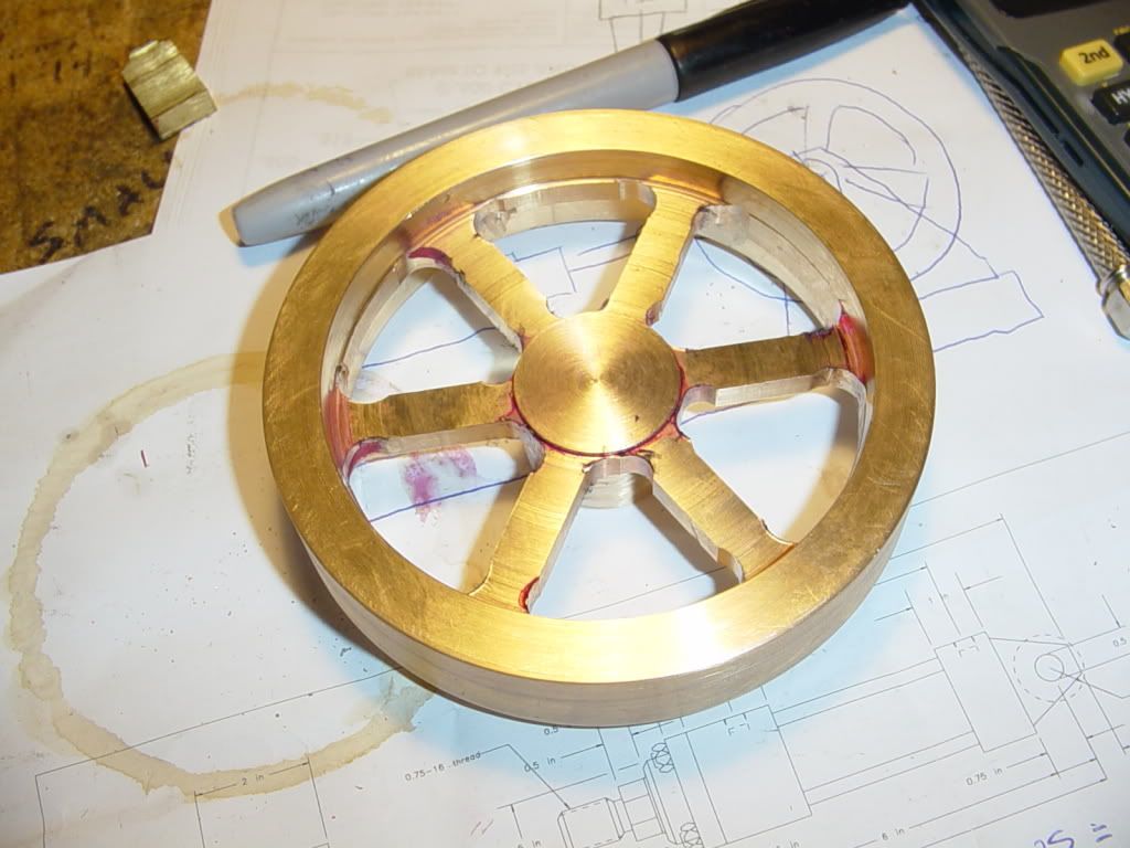
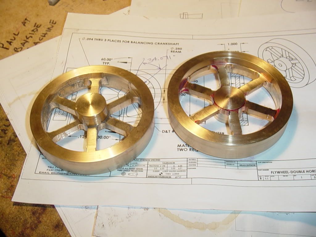
Congratulations and well done Brian, but I do hope that is not your lifes blood staining the work!!!

Hopefully it is just marking fluid.

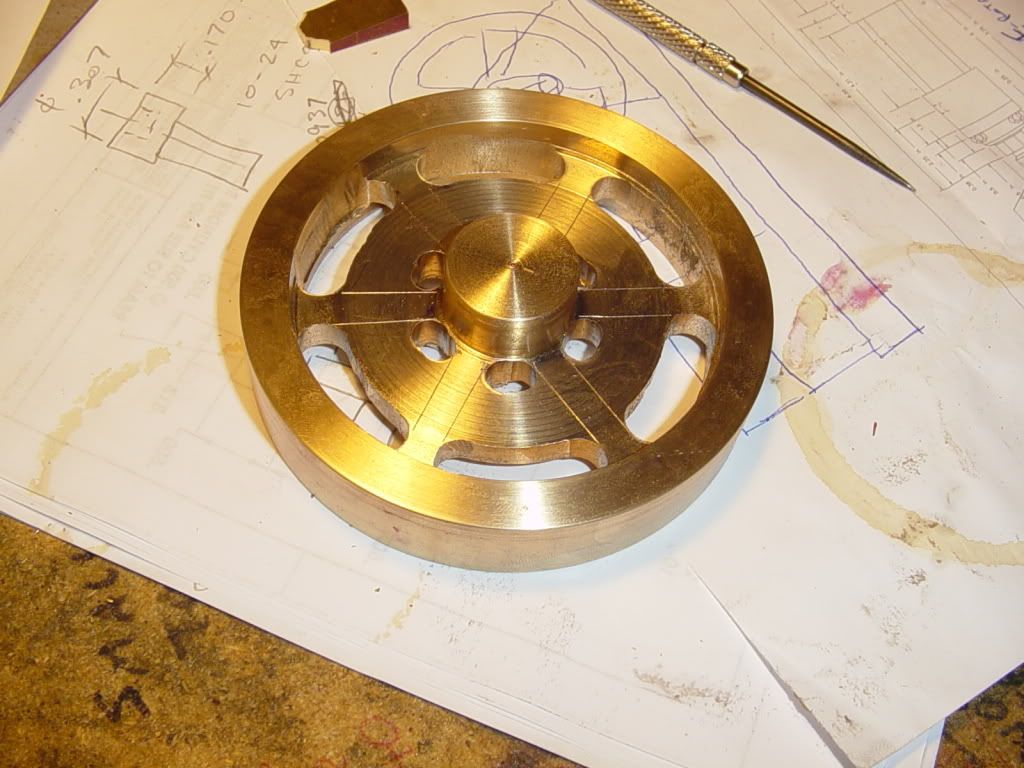
A bit of carefull work back on the rotary table would allow you to get rid of most of the remaining material and then finish with some filling.
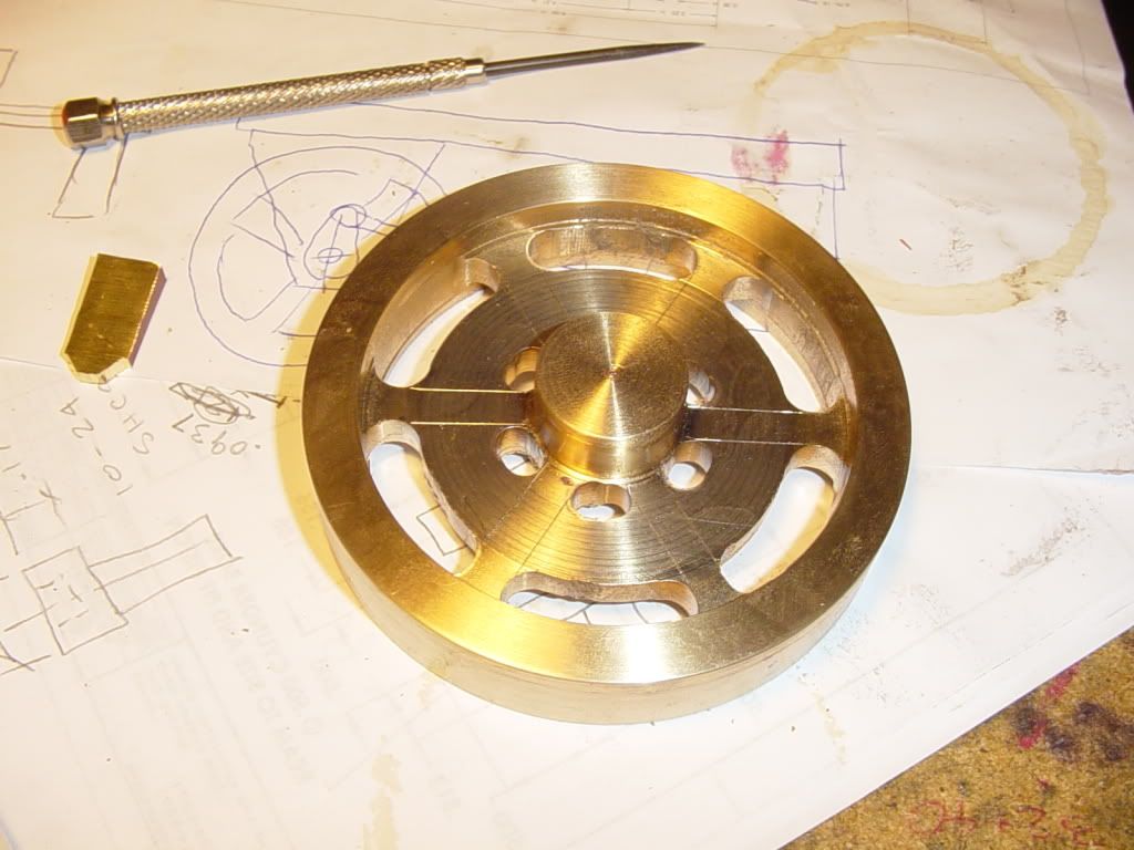
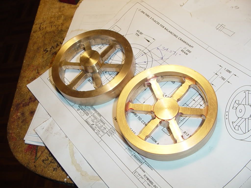
By the time you have finished the second flywheel you will be looking back and saying...what the hell was I so hung up about. ;D ;D ;D :p :big: :big:

On a side note: -

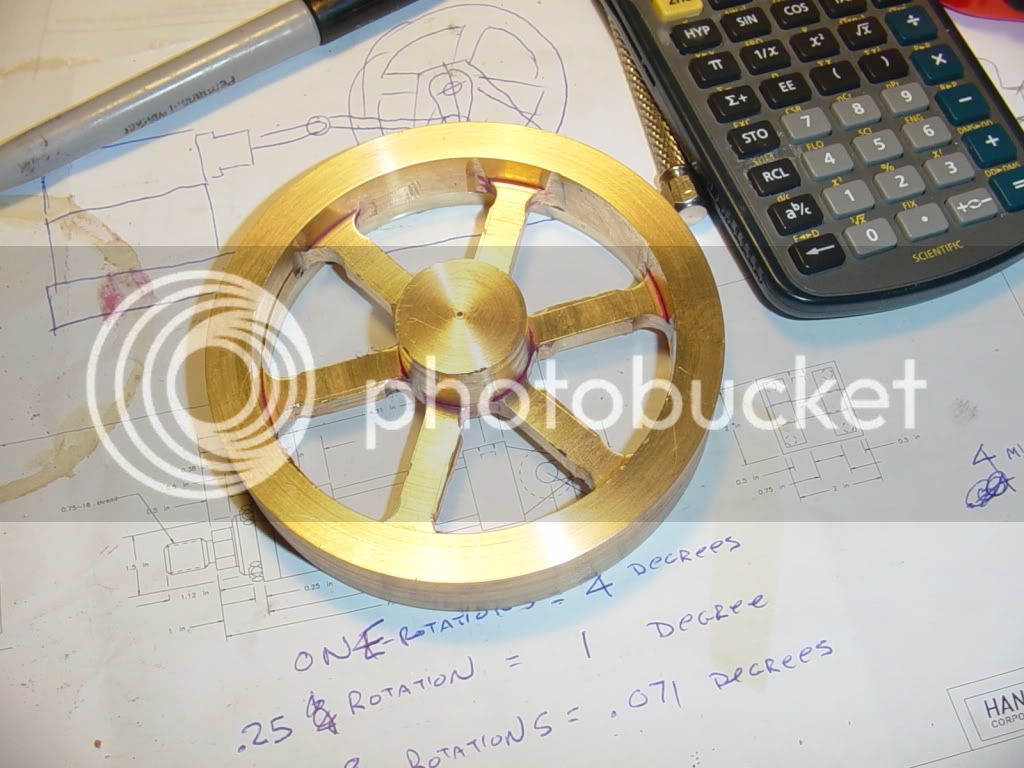
Are you sure about the Maths you presented?...... I agree with the final 2 minutes, but I got there from a different calculation.

On your drawing you have jotted 1 turn = 4 degs. of rotation, which would be correct for a 90:1 gear ratio table, a
typical ratio for a lot of the current models available.

4 degs = 240 minutes...divide by the 120 marks on your handwheel gives 2 minutes per div.

on the other hand: -

If, as you suggest in your write up, it is 4 turns per deg of rotation, this would be a 1440:1 ratio....I must say I have never come accross a rotary table with such a high ratio.... I am not saying they don't exist though.

If it is as you wrote, then 1 turn would = 1/4 deg.

1/4 deg = 15 minutes, which divided by 120 would give 7.5 seconds per div.

Just curious.

Keep happy.

Sandy.  ;) ;D
 
Brian,

I'm having trouble understanding what you wrote here. You say 1 handle turn = 1/4 degree of table movement (I find that hard to believe but more on that below...).
If what you say is true then:

1/4 deg = 15 min

15 min / 120 divisions = 0.125 min/division

1/4 deg per turn would mean that the table has a gear ratio of 4*360:1 = 1440:1. You would have to turn the handle 1440 times to rotate the table one revolution! I've never heard of an RT with such a fine gear ratio and, frankly, don't believe you have such.

Now, most of the Chinese tables have a 90:1 ratio. Thus one turn of the handle corresponds to 4 (not 1/4) degrees of table movement. Then we have:

4 deg = 240 min

240 min / 120 divisions = 2 min/division

Somehow, you arrived at the right conclusion (2 min/division) but your writeup doesn't mesh with the mathematics involved.

I'm not trying to be a nit-picker here but rather trying to help you avoid future mistakes based on an incorrect conception of how your table works.

 
I see Sandy beat me to the punch. :) Ah well, at least we both came to the same conclusion.

On my RT, Brian, every 30th division on the handwheel is marked with a number - 0,1,2,3 - which corresponds to a degree of table rotation. If yours has just 120 undifferentiated divisions, you may want to consider marking every 30th with paint or a punch dimple to make it easier to dial in integral numbers of degrees.

 
Told ya I was confused.--Yes, one complete turn of the handle equal 4 full degrees of table movement. Each of the small graduations equals 2 minutes. One quarter turn of the handle equals 1 degree of movement af the rotab. I was very confused, because the Chinglish instructions stated that each small mark was 1 minute, which is incorrect. I did figure it out correctly, then made a mistake when I posted.---And no, thats not my lifes blood, perish the thought.--That is layout dye. I did cover the visible side with layout dye and make scribe lines along where the cuts should be when I started to cut the straight sides of the window, just to reassure myself.
 
Not nearly as much drama with the second flywheel---yet anyways. Once I figured out the rotary table, things went a heck of a lot easier. I am amazed at how heavy these little buggers are. When I built the "beam engine at double scale" I made the 5" diameter flywheel out of aluminum, and was dissapointed in how light it was. Its a good thing this new engine is going to be twin cylinders--It is going to take a lot of "Chuf" to get these 4" diameter fellows turning.
flywheel-2slotscut001.jpg

flywheel-2slotscut002.jpg
 
Bravo Brian. Your flywheels look great. :bow: :bow:

Cheers,
Phil
 
Well done, Brian. A little clean up and you'll have some real bragging rights.

Steve
 
Brian,

Way to go man, great job
049.gif

Don't ever think you aren't a machinist :D
Best Regards
Bob
 
Isn't it just the best feeling when you're getting good results from a new tool?

The rotab is a complex beast that offers lots more learning opportunity, but this is a wonderful start. Pretty soon you'll be putting arcs of various kinds into all sorts of parts just because you can.

Cheers,

BW
 
Brian, great job! The RT is an amazing piece of equipment. There's just so much that can be done with one...

So, you have a crankshaft and now two flywheels... What next?? ;)
 
Tim
You have an excellent eye. I'm right in the middle of writing up a post showing how that very same type of flywheel is made. It should be up in another hour or so.

Steve
Hello - I am going to have a go at using my new rotary table to make my first spoked flywheel over the weekend (and probably a few after!) using Marv Klotz's excellent tapered spoke calculation program (thanks!) and wondered if you ever did the write up on the curved spoke creation?

Regards

Chris
 
Thanks Chris, for asking what I was going to ask before I got to your post.
I'm making patterns to cast a Rider-Ericsson hot air engine and want to make a curved spoke flywheel.
Chuck
 
Brian
When I did my first cutout flywheel, for Elmer's Pumping Engine, I, like you, had used the rotab very little.
I used Marv's program to do the calculations. Then, I put a Sharpie in a collet on the mill and did a "dry run." the Sharpie-drawn flywheel was perfect, as was the "real" one with an end mill. (thank you, Marv)
As with any new operation, it's a bit unnerving the first time. Go slowly, avoid interruptions ( phone off; no visitors). Work safely. Trust me, it will work.
My latest mantra when doing a new op is "It's just a piece of metal. I have more"
My other philosophy is to make one part until it's perfect ( or close enough). My current build, a Liney RV2, has just about enough "not close enough" parts to make a second engine.
 
Back
Top