Machining flywheel "windows" with rotary table on mill

Home Model Engine Machinist Forum

Help Support Home Model Engine Machinist Forum:

This site may earn a commission from merchant affiliate links, including eBay, Amazon, and others.
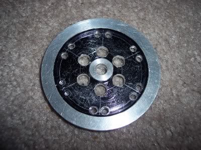
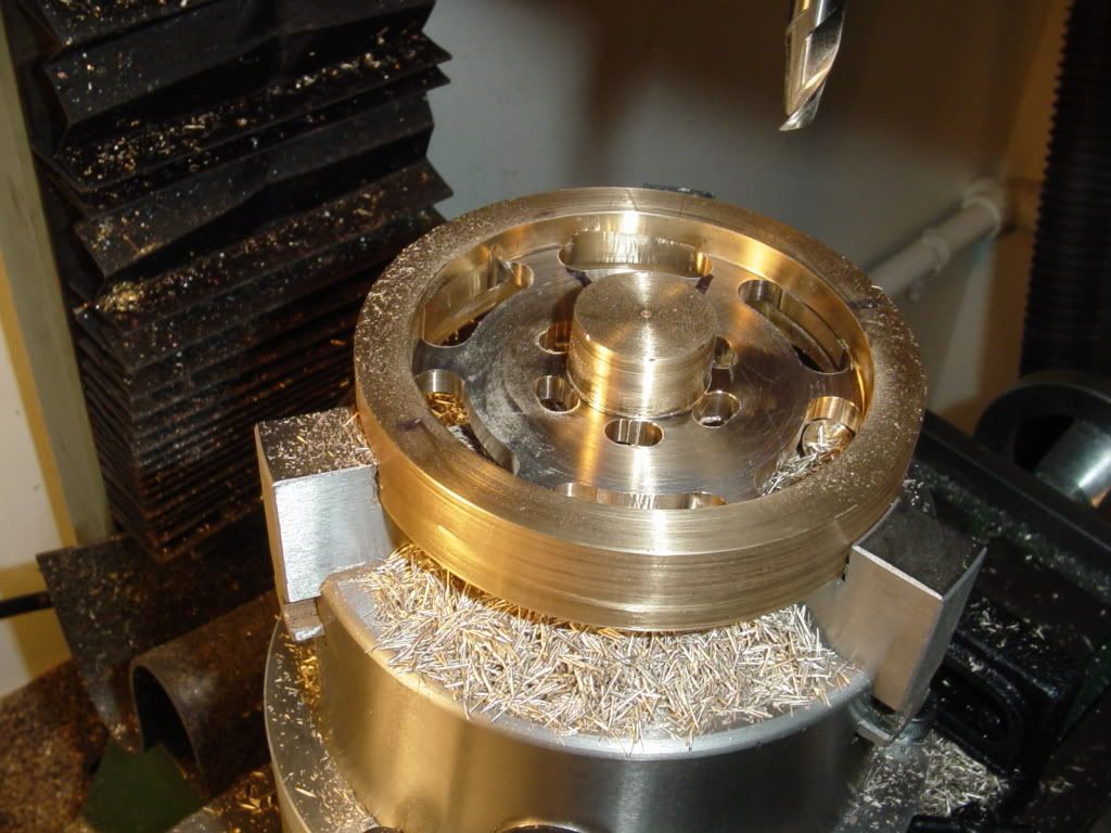
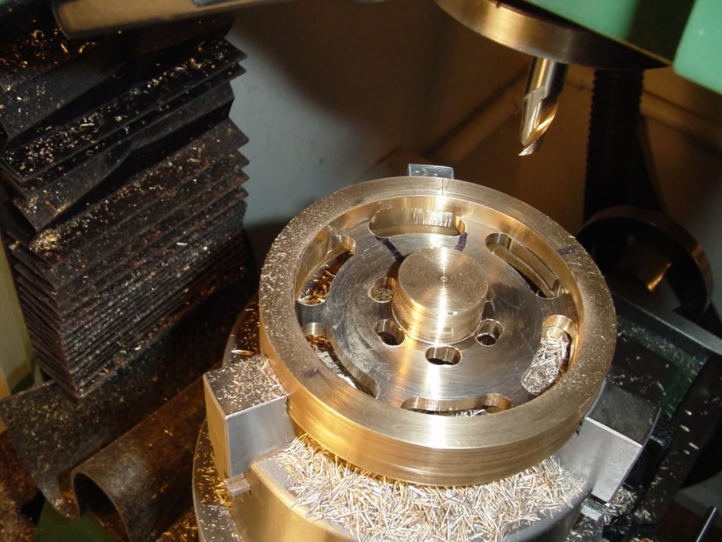
Regardless of how you make the cuts, it is crucial to get both the RT and the flywheel blank centered over the spindle first.

On mine I centered the RT using a DTI and indicating the inner hole. I was told that this more accurate than using the outer rim of the RT. Zero your dials/DRO once this is done and don't change them until the entire piece is finished.

To center my flywheel on the RT, I first drilled and reamed the center hole. I then mounted a drill or mill of the same size in the spindle, pushed it through the blank center hole, and then lowered the spindle and blank onto the RT where I could clamp it down. You can verify that all is centered by then rotating the wheel around the drill/mill; should be no binding.

For moving the tool to do the cuts, I found using the Y-axis to give better visibility.
 
Brian,

You've discovered why my FLYWHEEL program produces two solutions. The first is the mathematically correct one given the desired spoke widths. Almost inevitably, this leads to oddball angles between the two outer web holes - as you've discovered. Since exact spoke width is seldom critical, the program then goes on to compute a solution that produces integral spacing between the outer holes at the expense of a slight change in the spoke width.

You can, of course, do this yourself but the math, though trivial, is messy enough to raise the probability of computational error.
 
Brian
Round off the angle and then cut all tapers on one side only. Flip the flywheel over and cut the other 6 sides. The angles will match and you're head won't hurt...LOL

Steve
 
Assuming your outer hole angle to be rounded to 34 degrees, then the distance between holes across a spoke is 26 degrees.

To make it more "idiot proof", why not set the RT to 0, then make one hole at 13 and another at 347. Then rotate to 60 and make two holes at 73 and 47. And so forth. That's how I did mine, and having the same last digits on each pair of holes was a useful mental checkpoint.

Having all the critical points being even degrees makes everything easier.
 
kvom said:
To make it more "idiot proof", why not set the RT to 0, then make one hole at 13 and another at 347. Then rotate to 60 and make two holes at 73 and 47. And so forth.

That will work assuming you're not suggesting turning the RT in two directions. To avoid backlash problems you should only turn the RT in one direction. This would suggest a procedure where you make an ordered list of all the holes to be drilled and then drill them in sequence while always rotating the table in one direction.
 
Kvom...
Stand back... I think his head's about to explode....LOL

Steve
 
Good Lord!!!--And I thought "sweating bullets" was only an old wives tale---- I've got the first 6 outer holes in at 60 degrees each. Now if I can just understand the rotary table instructions on how to get a decimal of a degree---
 
I think at this stage I'd be taking Marv's earlier suggestion and breaking out a piece of mdf ;D

Good luck Brian ............... you'd best be quick though, don't think we can hold our breath much longer :eek:

CC
 
Brian
I feel your pain there dude....LOL. It got pretty intense here too. After the fact, it seemed like a lot of worry over something that was much easier than expected. Yeah... I needed a good shower and a stiff drink after that first session too.

Steve
 
Don't be afraid to be scared Brian! :D

As has already been stated here, layout lines on the part are a waste of time.
I always DO the layout thing myself.

Here's a perfect example from my "recycle box"

FlywheelOops.jpg


Lines are in the right places, but those would be some very WIDE spokes.
You'll notice the last two center drilled holes were never drilled.
It's kind of hard to do that when the piece is flying across the shop to the
"That Didn't Go So Well Corner."

Rick
 
Maybe now you guys can appreciate why I wrote a program to produce a complete cutting schedule for this task.

My first "freehand" attempt to make a spoked flywheel looked remarkably similar to Rick's "recycle box" example box above. Nevertheless, I didn't instantly discard it, as Rick did, but continued machining it to uncover other problems (hence my remark about doing a test piece first). That's why it had a huge gouge mark from where the newly-freed segment jammed between the endmill and the window creating enough torque to move the head on the round-column mill/drill. Hence my previous cautions about that final cut that frees the scrap piece.

On another note, I just noticed something. Look carefully at Brian's flywheel drawing and the innermost corner of the triangular window. Normally this is formed by drilling a single hole but Brian's drawing shows it developed from two overlapping holes. If he really intends to build it that way things are going to get a good bit more complicated for him.
 
rake60 said:
Don't be afraid to be scared Brian! :D

As has already been stated here, layout lines on the part are a waste of time.
I always DO the layout thing myself.

Here's a perfect example from my "recycle box"

FlywheelOops.jpg


Lines are in the right places, but those would be some very WIDE spokes.
You'll notice the last two center drilled holes were never drilled.
It's kind of hard to do that when the piece is flying across the shop to the
"That Didn't Go So Well Corner."

Rick

I hope you dont mind, but looking at your "mistake" made me think of a possible way to recover it.

FlywheelOopsfix.jpg


Just a few mins work in photoshop, imagine that the parts colored that beautiful green are the spokes, it'd make a pretty groovy flywheel. ( although a pig of a flywheel to machine !!! )

Tim
 
Tim
You have an excellent eye. I'm right in the middle of writing up a post showing how that very same type of flywheel is made. It should be up in another hour or so.

Steve
 
Also to recover, a second set of holes on the outside offset 30 degrees and the offending holes will be milled away when you make the cutouts. Gail in NM,USA
 
Cedge said:
Tim
You have an excellent eye.
Not really, I just like puzzles and also like form that flows, I used to do a lot of woodturning and I think that is where it comes from. Now if only I could make my hands ( and machines ) produce the flowing forms that I can imagine in my head!! :big:
I'm right in the middle of writing up a post showing how that very same type of flywheel is made. It should be up in another hour or so.

Steve

Well I really look forward to reading that as I'd love to make a flywheel like that someday.


Tim
 
Can you say "Nervous exhaustion'??? So far I have been successful. No, I actually didn't use any layout lines. I had quite a time figuring out just what the heck all the divisions on my rotary table meant, and how many marks represented one minute of arc, but I think I won. I bought a new 2 flute 3/8" endmill for the outer arcs, and found it really "grabby" as I went around the outer arcs. It acted like it was climb milling, and made my whole set up vibrate a couple of times, and like to scared me to death, but nothing broke and nothing bent. I advanced the rotary table in very small increments and held my breath---The flywheel web is 1/4" thick, and I was taking a full depth cut, with the end of the end mill actually extending about 1/8" thru the far side of the web. I am going to go upstairs now and soak my sore feet--they are not used to supporting a fat old man for 8 hours straight. I live my life in my computer chair most of the time, so my old dogs are really barking tonight. Tomorrow I attempt to cut the rest of the windows.
flywheel-slotscut001.jpg

flywheel-slotscut002.jpg

 
rake60 said:
Here's a perfect example from my "recycle box"

Rick, pull that piece back out for some really fancy spokes. I don't quite have it completely visualized but start by drilling a reasonably large hole on a line centered between two smaller ones so it gives a fair web thickness between it and the inner holes and falls just short of the rim. (The rim can be machined smooth later.) Now, mill a curve so that it comes from an outer hole and meets the new hole at a tangent then back down to the little hole on the other side of the new hole making kind of a "pointy end of an egg shape".

Once they're done and happy, you may be able to drill a really small hole somewhere between the newly milled cutouts just outboard of the inner holes and mill out a curve that matches the curve of the big holes but taking material out from between them.

If I'm visualizing this, you should wind up with a rather unique almost filigree spoke arrangement that absolutely no one else will have. Well, unless they read and can follow this pre-coffee IV description.

I don't have a CAD program loaded (or a scanner) or I'd draw it out for you.

BEst regards,

Kludge
 
Brian Rupnow said:
Can you say "Nervous exhaustion'???

You certainly can ............... pull up a chair and rest a moment ;)


Brian Rupnow said:
I was taking a full depth cut,

Well done Brian ............. enjoy a well deserved soak 8)

As for me ......... and this just my approach, and because my Mill is fairly small, .......... I would have done several passes to take out 1/4" of brass, each one would have been a lot quicker .......... so overall the time spent milling would probably be a little longer but, ........... a bit less stressful ;D

as I say ........... just my way, an that don't make it right.

CC
 
Brian, it looks great! Hang in there! No need to sweat that much over a little flywheel... It's not for the Space Shuttle!
 
WE...
You are so right... it's not for the space shuttle. It's more important than that... it's for HIS steam engine....LOL

Steve
 

Latest posts

Back
Top