Mach 3 spindle encoder?

Home Model Engine Machinist Forum

Help Support Home Model Engine Machinist Forum:

This site may earn a commission from merchant affiliate links, including eBay, Amazon, and others.
I've been playing with metric thread pitches and checking them with a thread gauge...all spot on.

I must confess that I am rather an idiot....I had been putting off cutting SAE threads because mach 3 want you to enter the pitch in .000 of an inch. It took me about an hour of critical thinking and looking for charts on the internet before I realized that if you divide 1 inch by the threads per inch you get the number you need haha :eek: I never work with SAE fastners haha.

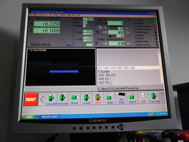
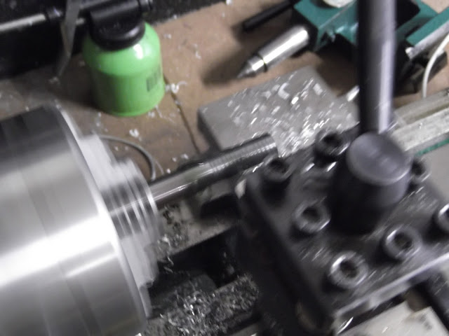
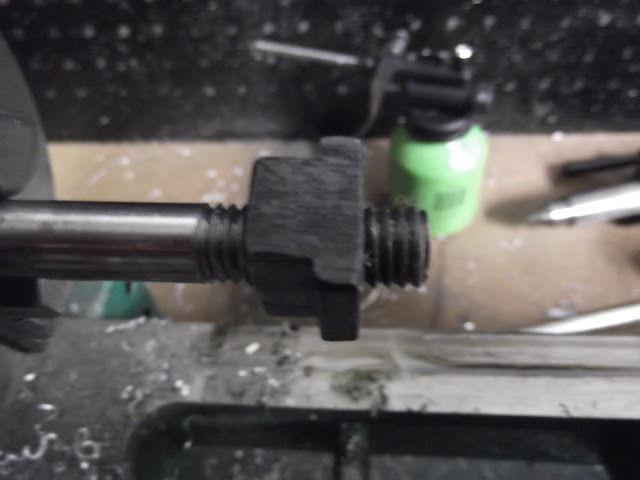
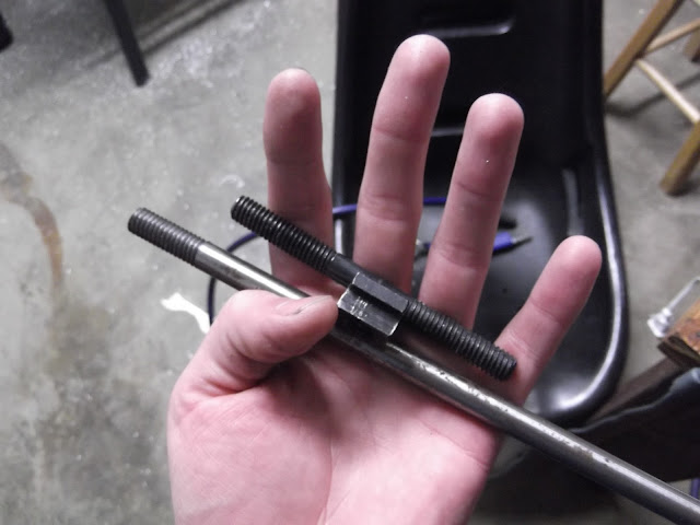
Anyways here's some pictures of me cutting 3/8 by 16 on a piece of 3/8 drill rod.
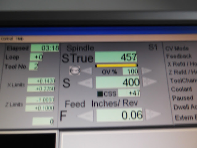
DSCF0236.JPG


Spindle speed

DSCF0237.JPG


DSCF0232.JPG


DSCF0235.JPG


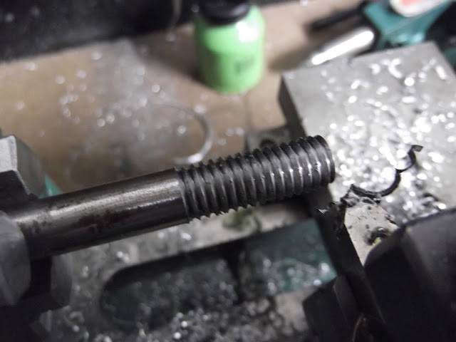
I had a t-nut from my mill to check it with.

DSCF0238.JPG


DSCF0240.JPG


Success! ;D

 
Speaking of being an idiot (which you aren't obviously) I have never even tried to thread in Mach. I'm a new user and haven't tried many of the wizards yet.

Is it a pretty simple fill-in-the-blanks operation? You tell it how many passes & depth of cut, etc and it automagically makes a pass, backs off the tool, returns to start, plunges the tool a bit makes a pass, etc, etc...all the while staying synched up so the tool matches the thread each time?

What CAM software do you plan to use for regular profiling work?

ps: I like how you went straight to drill rod & cut a nice thread. No easy aluminum or plastic for you! :bow:
 
Hi Rusty

Your starting point of resistor 1 @ 330 ohms and resistor 2 @ 2K2 ohms sounds like a good starting point - I would have suggested similar values, but as you discovered - NOT all photo-interupters are equal.

In your example, resistor 1 determines the amount of current through the diode and therefore the amount of light emitted - this also has an influence on the fall time of the signal. Resistor 2 is the "Pull-up" part of the signal chain - the higher value the slower the signal rises ...!... this is the main reason why your narrow slot in the disc didn't work - 10K will give you a slow rise of the signal. Don't get me wrong - your solution with a tab is much better !!!!

The diode will work fine with up to 50mA current through it - (measure supply voltage - voltage measured over the diode) / resistor = current. Some will accept more current, but for this, you need to read the data sheet (read model number on it and Google it). As for resistor 2 - 10K is the max value if it is to work with a parallel port and the min value is around 100 ohms (a too small value will destroy the transistor in the device). All these values are with a 5 volt power supply, as in a "normal old style parallel port".

Edit : I forgot to mention that the photointerupter prefers to work in the dark - so to speak. Other light sources might interfer with it.

Hope this helps you and others understanding the subject a little better.
 
Admiral_dk said:
Hi Rusty

Your starting point of resistor 1 @ 330 ohms and resistor 2 @ 2K2 ohms sounds like a good starting point - I would have suggested similar values, but as you discovered - NOT all photo-interupters are equal.

In your example, resistor 1 determines the amount of current through the diode and therefore the amount of light emitted - this also has an influence on the fall time of the signal. Resistor 2 is the "Pull-up" part of the signal chain - the higher value the slower the signal rises ...!... this is the main reason why your narrow slot in the disc didn't work - 10K will give you a slow rise of the signal. Don't get me wrong - your solution with a tab is much better !!!!

The diode will work fine with up to 50mA current through it - (measure supply voltage - voltage measured over the diode) / resistor = current. Some will accept more current, but for this, you need to read the data sheet (read model number on it and Google it). As for resistor 2 - 10K is the max value if it is to work with a parallel port and the min value is around 100 ohms (a too small value will destroy the transistor in the device). All these values are with a 5 volt power supply, as in a "normal old style parallel port".

Hope this helps you and others understanding the subject a little better.

Thank you for sharing, that certainly gives me a better understanding of what I was dealing with. I may have to take a few courses in electronics, they are quite interesting.

Regards,
Eric
 
DICKEYBIRD said:
Speaking of being an idiot (which you aren't obviously) I have never even tried to thread in Mach. I'm a new user and haven't tried many of the wizards yet.

Is it a pretty simple fill-in-the-blanks operation? You tell it how many passes & depth of cut, etc and it automagically makes a pass, backs off the tool, returns to start, plunges the tool a bit makes a pass, etc, etc...all the while staying synched up so the tool matches the thread each time?

What CAM software do you plan to use for regular profiling work?

ps: I like how you went straight to drill rod & cut a nice thread. No easy aluminum or plastic for you! :bow:

It really is pretty simple, there's is a tab at the bottom of the threading wizard that directs you to more choices such as cut depth, that are not on the main screen. On the main screen you just pick your spindle speed, starting positions, thread pitch in thousanths of an inch, and thread depth. It calculates the number of passes. Run a dry run to make sure it won't crash anywhere. Hit the button, and away it goes!

I've played with several cam softwares and have not found one that I really like 100%. All the ones I tried were catered to milling and barely dabbled in lathe stuff. I've download the latest version of Lazyturn, by the Mach3 folks. I'm going to try that next after I finish reading the huge manual. It seems to have a good following. I'll let you know.
 
I am working on a new set of Turn wizards for Mach. I have them prettywell complete, just need to do a few loose ends and I will release them.

In mine threading is based on a table- you simply select a thread size, 1/4-20 or 8-32 and the wizards fills in the rest. The table is a user editablke file so you can put in whatever values you use.

You can see a demo of the wizard at http://plsntcov.8m.com/CNClathe/CNClathe1.html

Id like any feedback on them.
 

Latest posts

Back
Top