Well at this point I had a circuit, but nothing to hook it to. I needed 5 volts DC for one connection to my board, another wire was needed for my ground. And lastly I needed my signal wire. Lets start talking about where to get 5 volts DC from. Machs instruction say some people get this 5 v DC from gaming ports and usb ports and such. All of this sounded too hard to me, I'm pretty lazy.....ok I'm REALLY lazy. I googled "what is 5v DC in a computer" and came up with a nifty little wiring diagram telling me that purpose of the computers power supply turns 110v ac into various DC voltages and distributes them all over the computer. Of the 3 I remember, it said yellow was 12v, red was 5v and black was ground. From my recollection, there was always a bunch of extra plug-ins leading off of power supplies to feed extra disc drives and such.
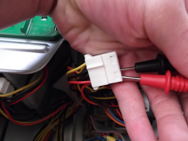
I had an extra computer handy so I got it out and opened it and found that indeed that was correct, and would actually be a really handy and easy place for me to take 5 volts and a ground from without having to cut any wires or anything. (I hate cutting wires, it seems so permanent)
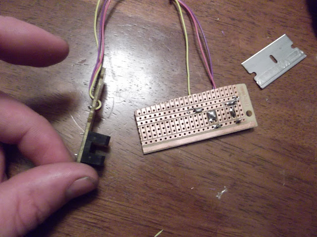
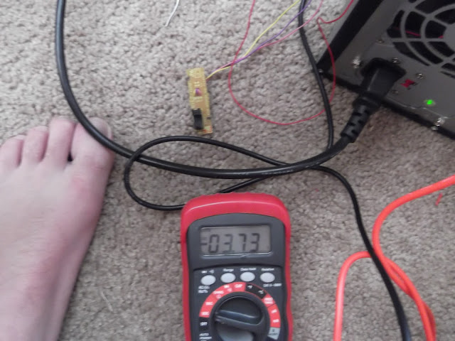
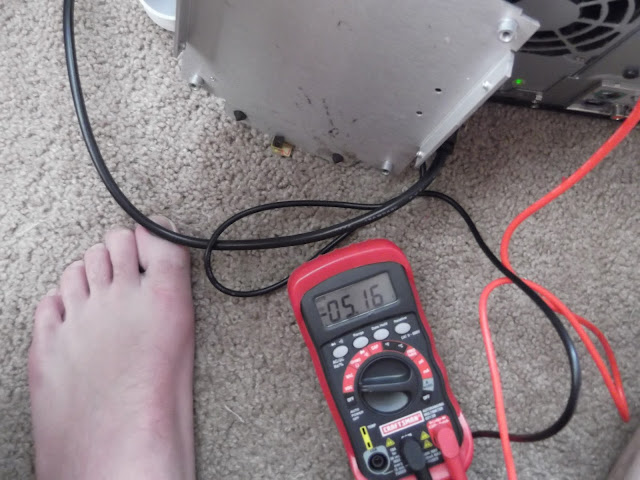
I went ahead and hooked up my circuit to the 5v power and ground, I left the signal wire off, and hooked my red voltmeter lead to it, black was on ground. Remember this was my first circuit with R1 at 330 ohms and R2 at 2.2K ohms.
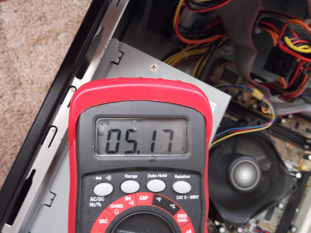
With no interruption in the beam of light I had a voltage of 3.73 dc (it reads negative because I never pay attention to what lead is in my hand and ignore polarity symbols)
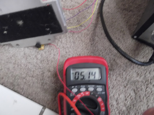
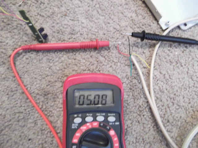
With the beam interrupted I had my 5V DC
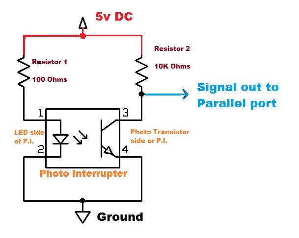
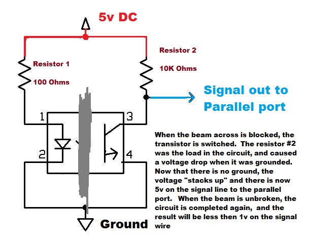
This will NOT work....why? As we stated earlier, mach tells us that for the computer to recognize a low input, it must pull the voltage down below .8 of a volt, were at 3.73. The computer cannot tell the difference between a 3.73 signal and a 5 volt signal, as they are both over the 2.4v High signal threshhold. Why is this happening? Well, if I understand correctly, If the original resistor was 2.2K and could only take away 1.3v there is a resistance in that circuit that is quite larger then that and its taking most of the voltage....like 2 lightbulbs in a series circuit. I assume the resistance must be internal to the photo transistor side of the photo interrupter. Its possible to voltage drop the circuit, I reckon, you couldnt ohm it, because the circuit must be powered to work and you cannot ohm check live circuits. Never the less, I attempted several combinations and ended up settling on R1 at 100 ohms and R2 and 10k ohms. For note, I found that I had to change R1 to the 100 when I had hooked up the signal wire to the circuit. The port actually had about 2 volts on it and was backfeeding I reckon. I'll get to that later.
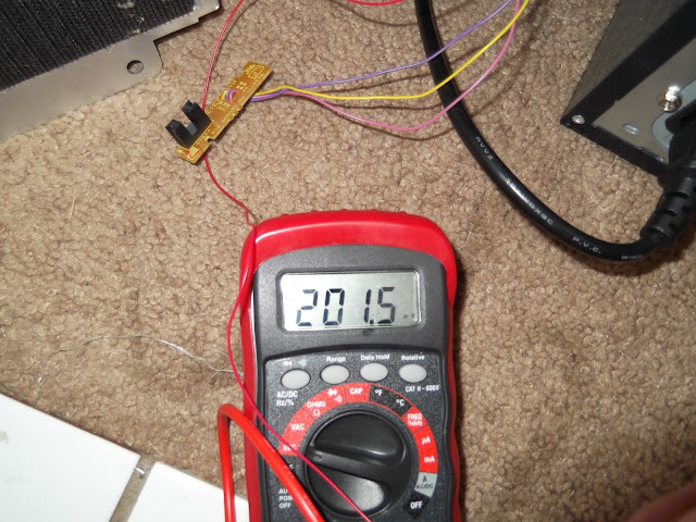
Now I have unblock 200 mV or .2 Vdc. This will trigger a low signal
And blocked we get our 5v back for a high signal.
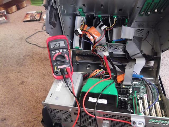
Got out my computer that actually runs my lathe, double checked its voltage of internal connectors. 5v as well.
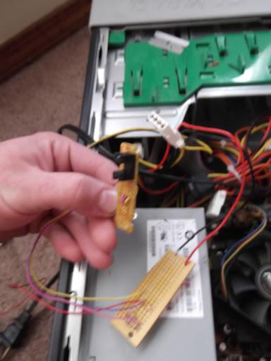
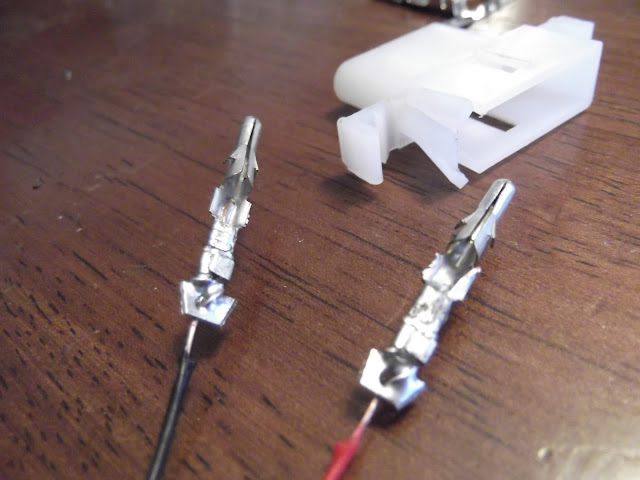
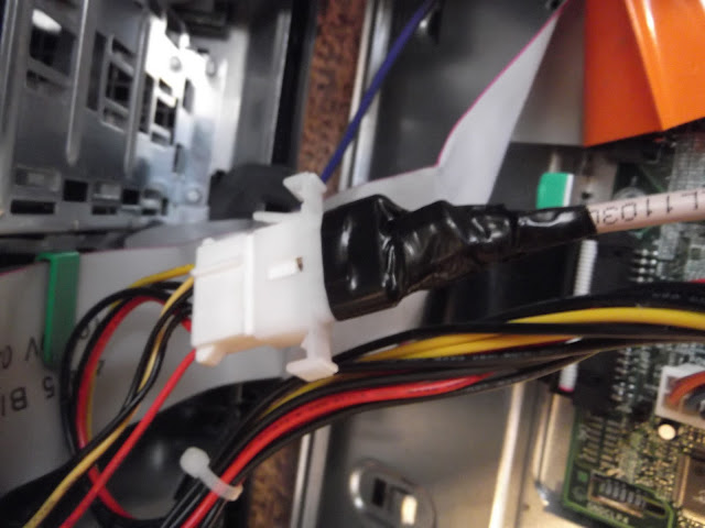
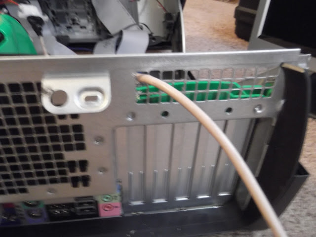
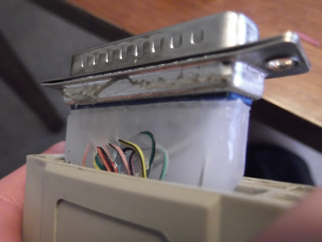
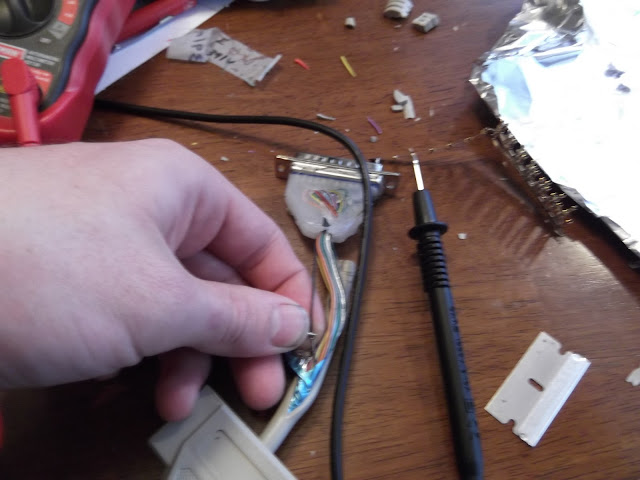
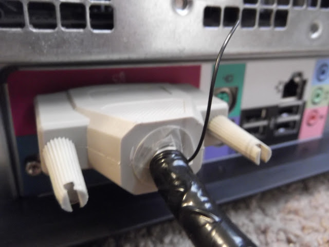
The wire I'm actually using is telephone wire, I came up with a huge spool of this for free years ago, have been trying to give it away and no one will take it. I'll never use it all lol. I went to radio shack and bought a connector to plug into the power supply outlets. Double checked my polarity.....got it wrong anyways, and had to pull the pins and try again. Solder all wire connections, insert pin and plug and play. The wire merely leads out of the case and gives me a place to get 5v dc from and a known good SEPERATE ground
That probly freaks out modern technie gurus, I can see the look on their faces now. haha