Wes,
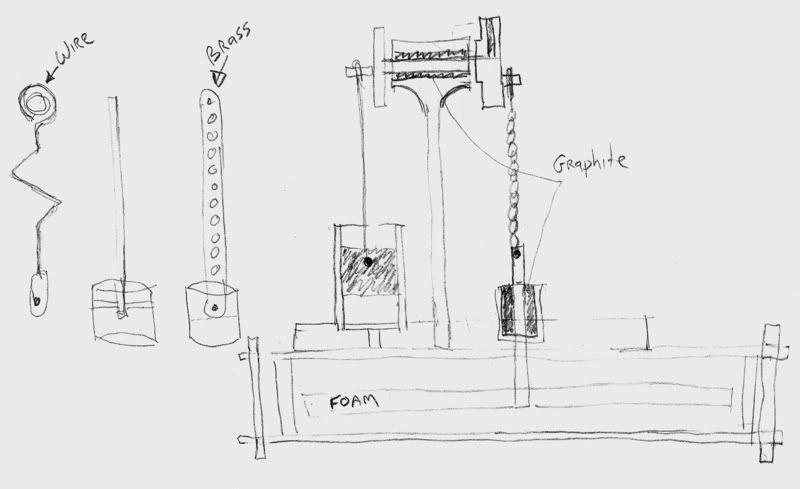
Maybe I misunderstood you. An LTD Stirling is unlikely to have the power needed to flex a piece of tubing (if that was your intent). The connecting rod needs to have a very low friction connection. Exactly how you establish that is a design detail but it must be as low weight and friction as possible.
Stirling engines come closer than most engines to operating on a true Carnot cycle. That means that their efficiency is given by:
efficiency = 1 - Tc/Th
where Tc and Th are the cold and hot temperatures respectively (expressed in degrees Kelvin). Taking:
Tc = 32 F (ice) = 273 K
Th = 100f (sun warmed) = 311 K
we have:
efficiency = 1 - 273/311 ~= 12%
So we're talking about engines that, at best, can only convert about 10% of the energy they receive into useful work. (In fact, it's absolutely astounding that they can be made to run at all.) With that sort of dismal performance, anything you can do to reduce friction is very important. Never attempt to lubricate an LTD. The viscosity of any oil will overpower the engine. That's why the self-lubricating quality of graphite is so desirable.