Looking for Advice.

Home Model Engine Machinist Forum

Help Support Home Model Engine Machinist Forum:

This site may earn a commission from merchant affiliate links, including eBay, Amazon, and others.

Micro-Eng

Micro-Eng
Joined
Apr 16, 2018
Messages
4
Reaction score
0
Dear Friends,

Hope everyone is having a great time.

I am from India, work as a biologist. I have NO engineering background whatsoever, but like to pass my time, tinkering with my honda CBF 150.

I have this idea for a new 'Type' engine, but dont know if it would work.

My idea is to combine a cylinder/Piston assembly (Suck/compress fuel air mixture) and pass it to a parallel chamber for ignition/exhaust. The pressurized escaping exhaust spins the flywheel. Of-course, plenty of valves are required throughout to minimize leaks and blowouts.

I have many questions here,

1) Has this been previously tried ?. Any pictures, models, links ?
2) what are the short comings?, benefits ?
3) Would anybody from this group be interested in making a working miniature model. I am curious to know how my idea would look like.

Thanks in advance. I hope to read your valuable comments.

Cheers.
 
Hello Micro-Eng
Could you explain closer why you want to move air-mixture
to a parallel chamber?
Can you add a drawing of your idea?
 
Hi Kadora,

Thanks for your quick msg.

I believe a piston connected to crankshaft is innately unbalanced (causing power loss, engine vibrations etc). Making the combustion in a separate (smaller) chamber, eliminates this.

Am working on the drawings, will post soon.

PS - I dont know any CAD, so struggling with MS-Paint
 
Hi Kadora,

I just noticed you live in slovakia. Currently I live in Trebon, Czech republic. Any possibilities that I could visit your place, we could discuss my idea over a coffee.
 
Hi Charles/ Kadora,

Its not a split single. Pls find a rough drawing (attachment) of what I have in mind.

Is there someone who could make a better 3D CAD (animated) version for me.

Appreciate your comments. Hope to hear more comments.

Rotary (like) engine 1.jpg
 
I love it when people have new(to them) ideas. There are often many reasons why they don't work and have often been tried before but just sometimes someone gets it right and we sit there thinking I wish I'd thought of that.
In this design the cylinder on the right is a simple compressor and I can't see how the rotor on the left can generate the power to drive the compressor. If it was a simple cylinder and piston on the left it would be more akin to the split single. DKW made one type and I believe Villiers made one too. These were two strokes.

dkwss250ss350090jpg.jpg
 
hello Micro-Eng
I like new ideas - even I am looking for a new project/idea
what would catch my heart BUT....
I think that your idea will not probably work
because pressure in parallel chamber // after ignition //will be the same
on right and left side of the rotor so rotor will not be able to move.
If there will be small pressure difference - say higher pressure on the right side
of the rotor - then rotor after roughly 90 degrees movement in clockwise direction will stop.
Please take it as my consideration only maybe I am wrong.
 
Micro Eng
to echo thoughts already expressed - In my study of motor design over the last 150 years, I see that thousands of brilliant minds (just like us ;) have come up with almost every possible permutation of engine, steam, IC etc. Some ideas are pursued for years or decades. I was particularly interest in rotary valves - still am. There are reasons that IC engines look the way they do, its kinda Darwinian, bad ideas died off.

That's not to say that there aren't possibilities, forgotten ideas that might be newly advantageous, but as has been recommended to me here, its useful to do some historical research. I suggest to look at Doug Self's wonderful site http://www.douglas-self.com/MUSEUM/museum.htm
 
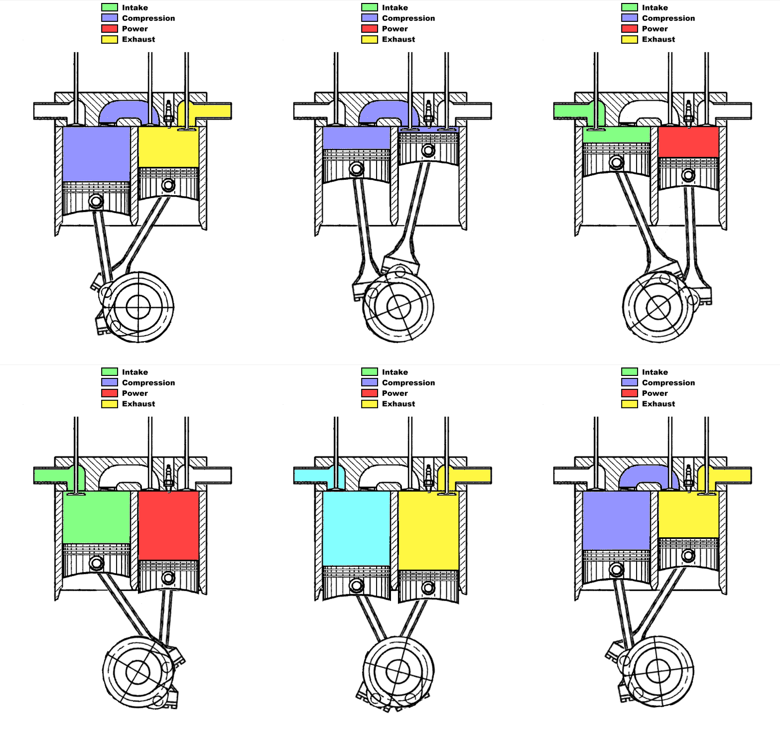
I believe that Scuderi Engine is what would be closest to what you want to accomplish. It allows for one cylinder dedicated to compressing air whilst another cylinder is dedicated for power and exhaust.
Scuderi_Split_Cycle_Engine_-_Cycle.gif


In your drawing, the power rotor is concentric with its housing so even when rotated, there is no volume change which means work can't be extracted (Tesla turbine is an exception to requiring eccentricity).

An alternative would be to have the exhaust head straight to a turbine which is mechanically connected to the reciprocating compressor with a few reduction gears. That has been done on an aircraft engine I believe. Can't remember its name though. downside to this is that it only extracts work when there is a lot of exhaust flow since it is not a positive displacement pump like a piston is in the Scuderi. That means likely low efficiency at low power.
 
The rotor will not works and the combustion pressure does not force the rotor
to rotate. The pressure is similar everywhere in a closed room and does not rotate
the rotor by expansion from combustion. :D

rotor.jpg
 
Back
Top