An air cooled, cross valve 360 Twin in the inventory now. Bigger pistons, heavy duty crankshaft, some cast iron and maybe a couple items you have not seen before. The Internal Breeze story starting this weekend.
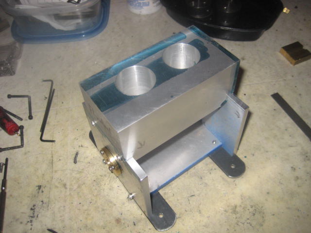
Two different styles of framing I use for I/C will be a combination of both for the Breeze. Two end plates, a base plate and the deck plate is gone, the engine block in its place.
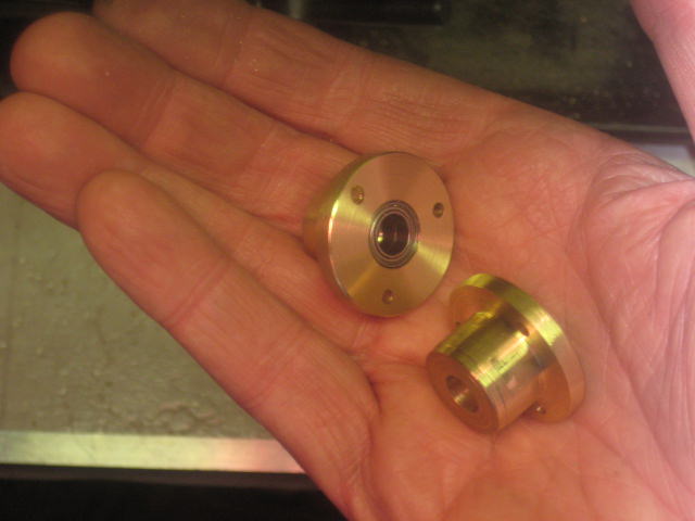
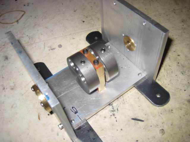
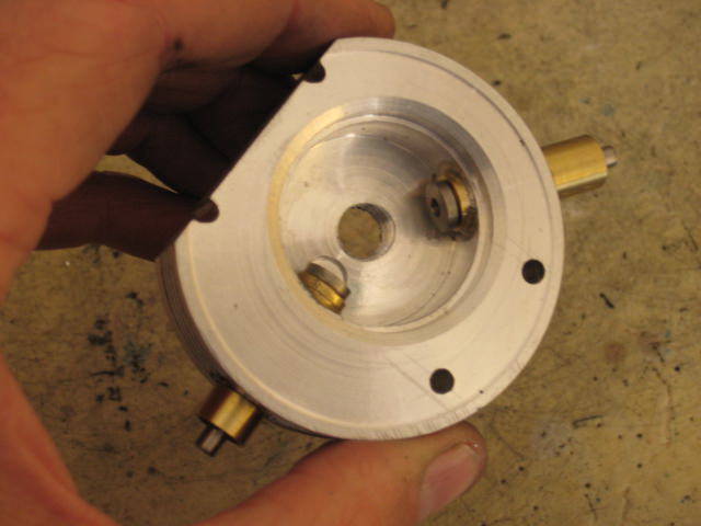
Brass bearing carriers in the end plates contain a pair of R1810ZZ bearings for the nose of the crankshaft and at the flywheel end the carrier has an Oilite bushing. I feel bushings are more supporting for the heavier flywheel end though rollers work fine too and I have a dozen to use up someday.
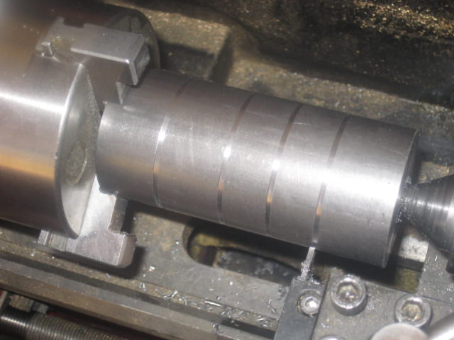
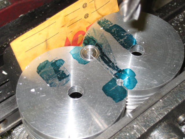
Crank webs are fabricated with 12L14 steel, 1.75in. dia. Shafting is .312in. CR and there are three main bearings.
Shown here scoring for their height. The center segments are shorter to accommodate the bore centers with a center bearing of brass between them.
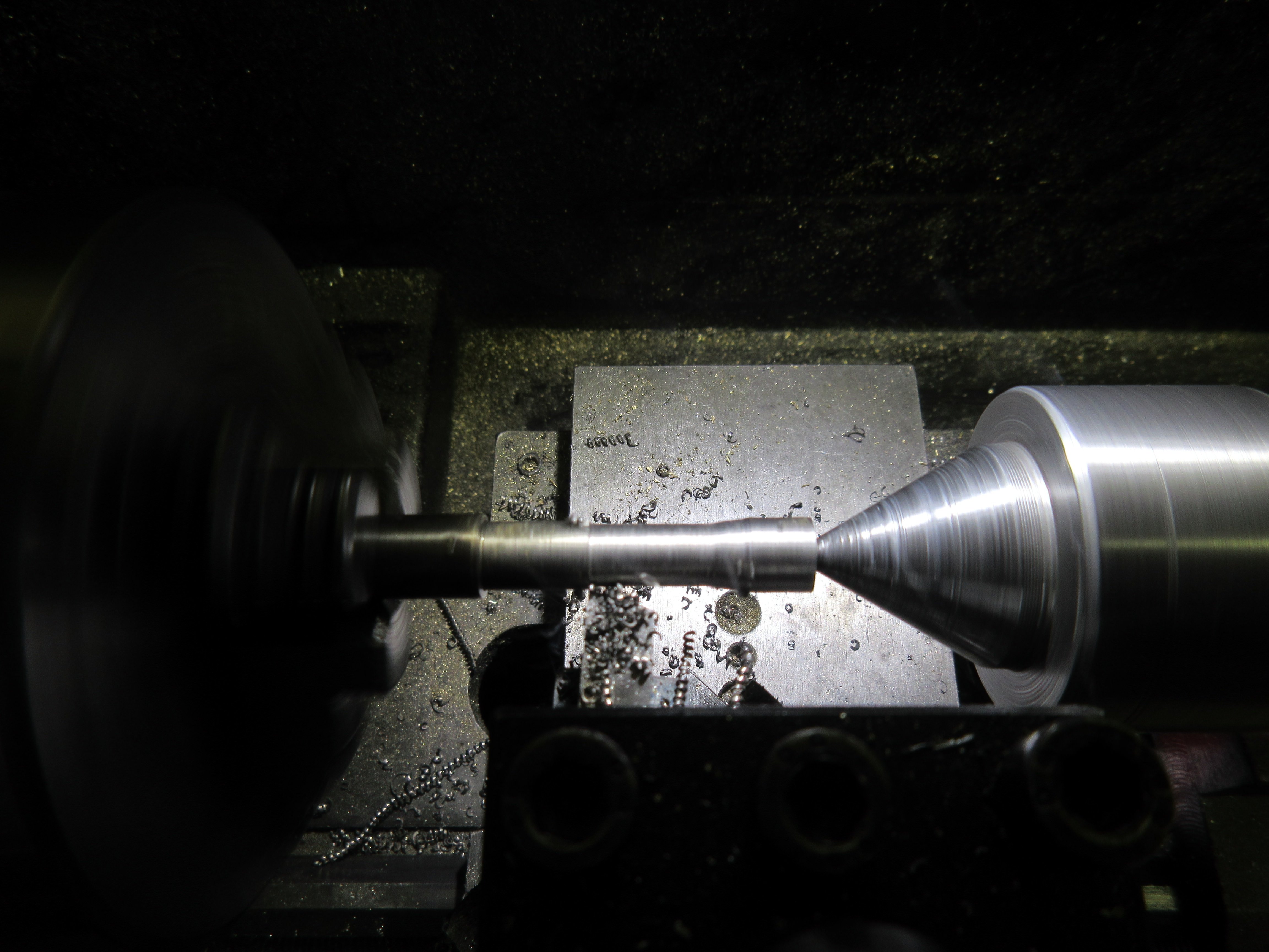
Setting up BREEZE with a 1.125 stroke with .250 throw pins of CR.
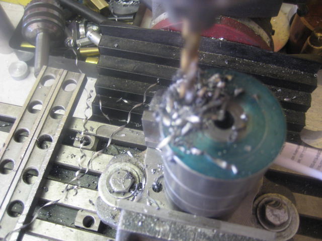
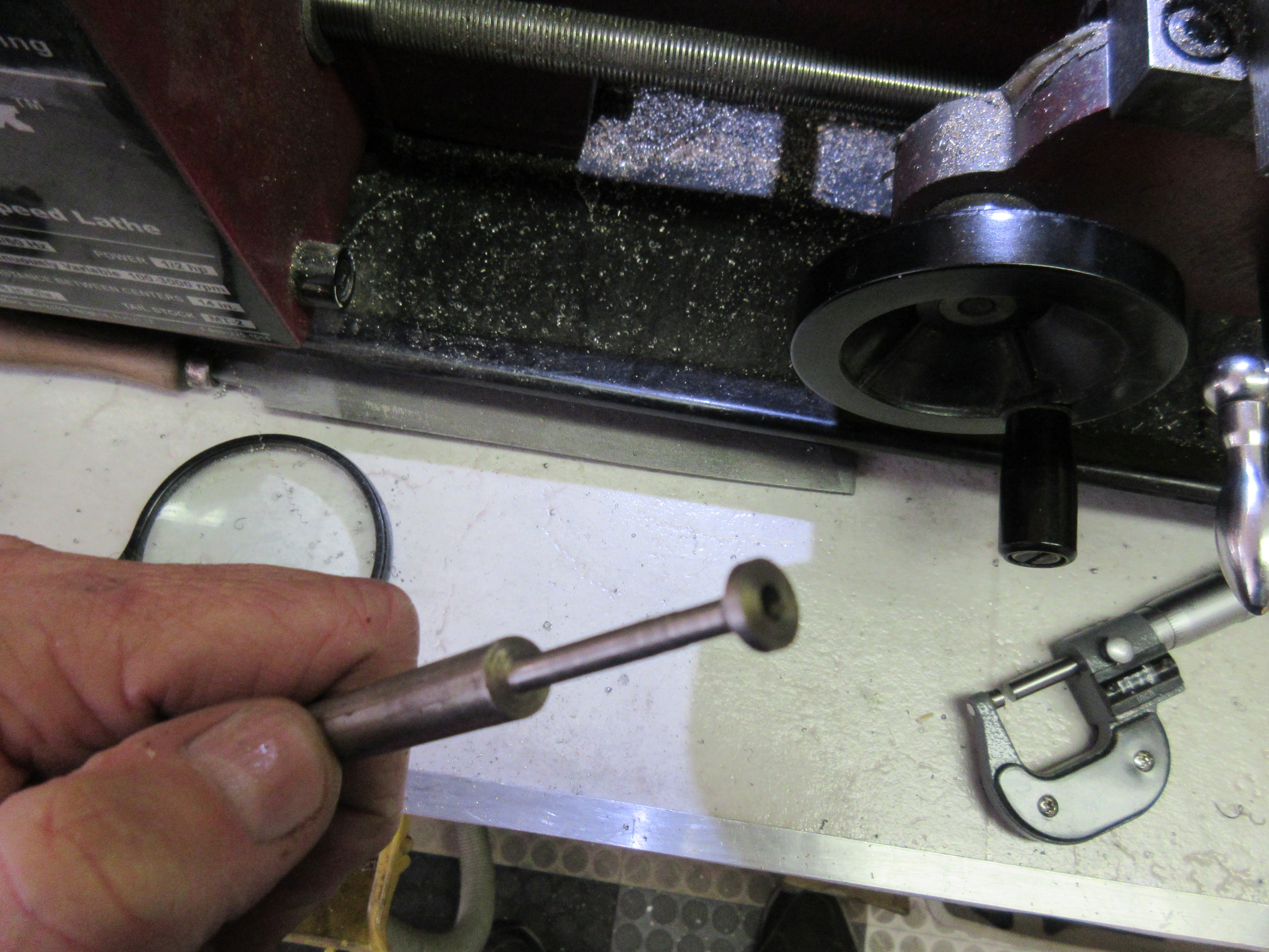
When the rod / piston assemblies are done, they will be weighed. The webs will be through drilled near the throw pins the calculated diameter for rotating balance then.
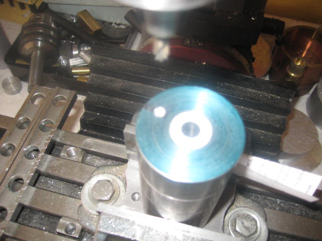
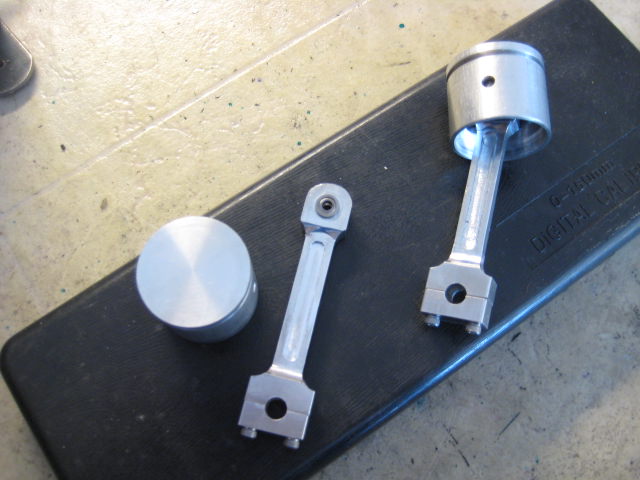
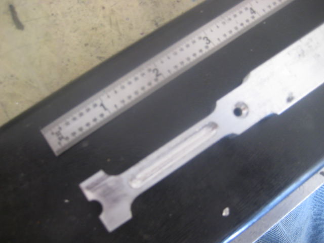
Up sizing the bore with 1.25in. pistons. The rods start as 3/8 X 3/4 in. aluminum flat stock. The small end has a pair of R144ZZ flanged bearings. The big end, no insert. Last couple engines with the rod as its own bearing surface trouble free. If I get any kind of a squeek outta them, I give it a shot of WD40. On BREEZE, I have drilled into the beam (#57) from the bearing surface straight up and intersected that hole with a diagonal drilling from just above the rod cap bolt . Tapered it out with a center drill that fits the nozzle straw from the WD40 can. Still makes a mess spraying outta the can.
Eighth inch piston pins join them to the rods locked to the piston with 6-32 set screws and blue loctite. I had 4-40's in there with no loctite that got loose and ate the bearings on a run. They ended up at 1.7oz. each complete. Using plumbers O-rings.
Stack them in the vice and sculpt them with a roughing mill.
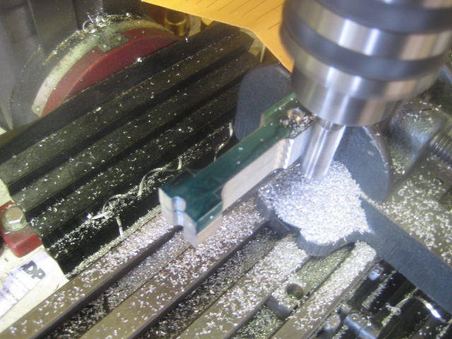
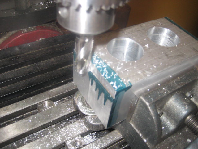
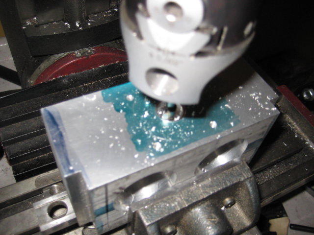
Boring the block for the cylinders begins. Two inch bore centers are off set on both x & y from the four corners.
More length on block from the front cyl. to the end plate for a possible points cam on the crankshaft and clearance for the ign. points which are on the inside of end plate.
And some extra width along the block length for valve train components. In the first step, the block is thru bored to the diameter plus of some thin wall DOM cylinder liners...................
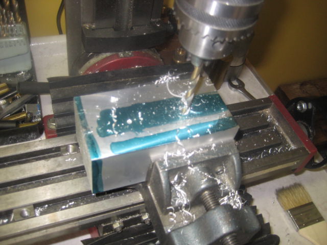
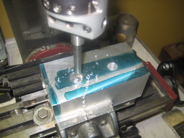
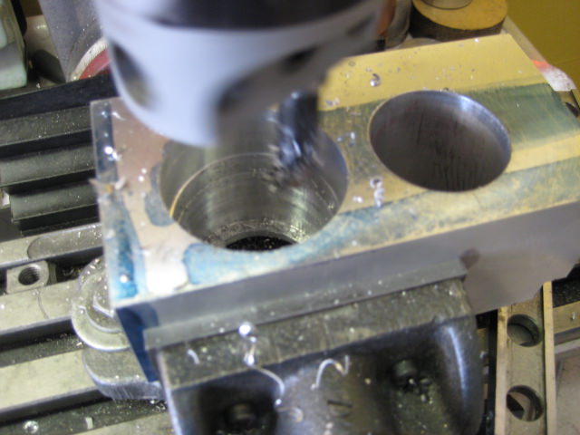
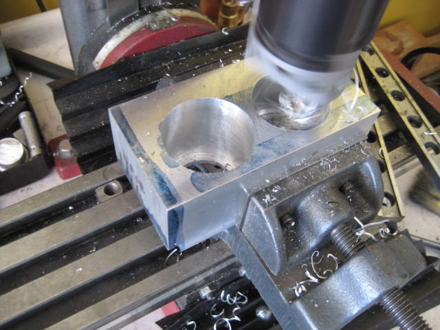
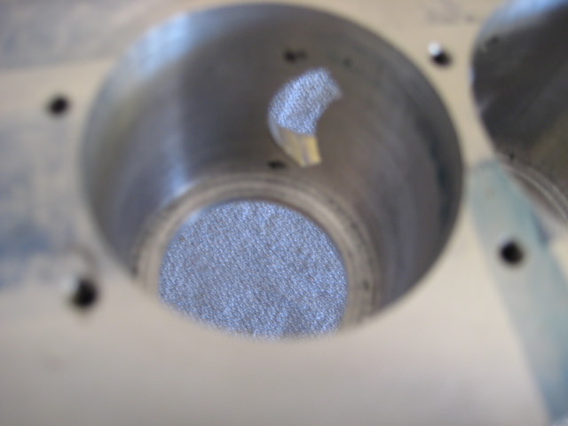
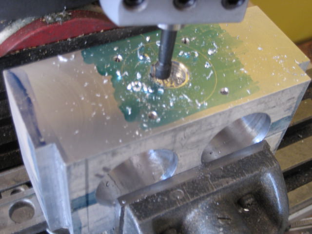
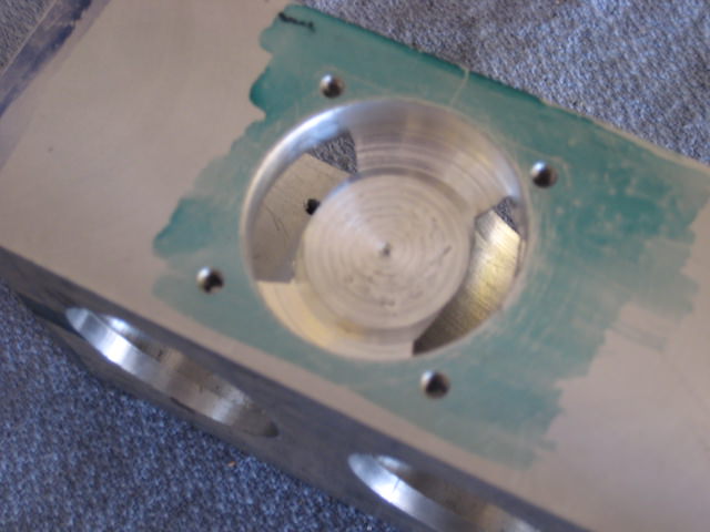
The boring for the liner/ radiator. Some shallow fined radiators will be fitted into the block.
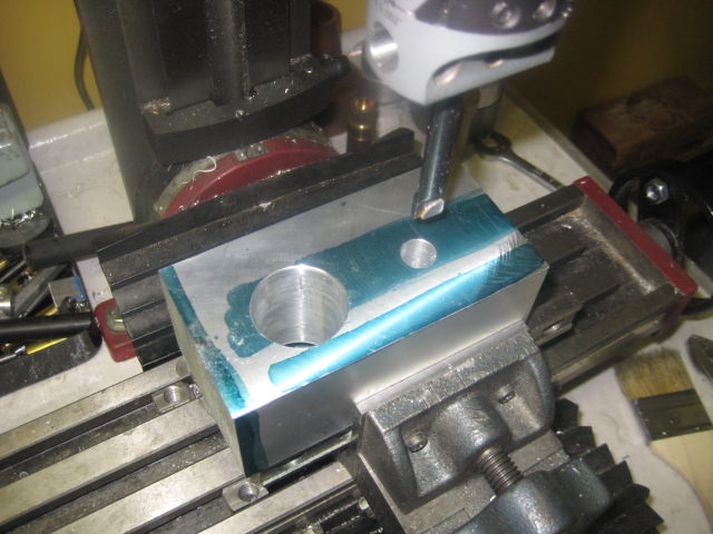
The block is bored diameter plus for them to a point about 3/16th inch from the bottom. The liner passes thru and the radiator seats in block on a drop fit.
No need to polish the radiators as they are not seen.
scratch.gif.....Radiators inside of block?.....What you up to here Longboy?
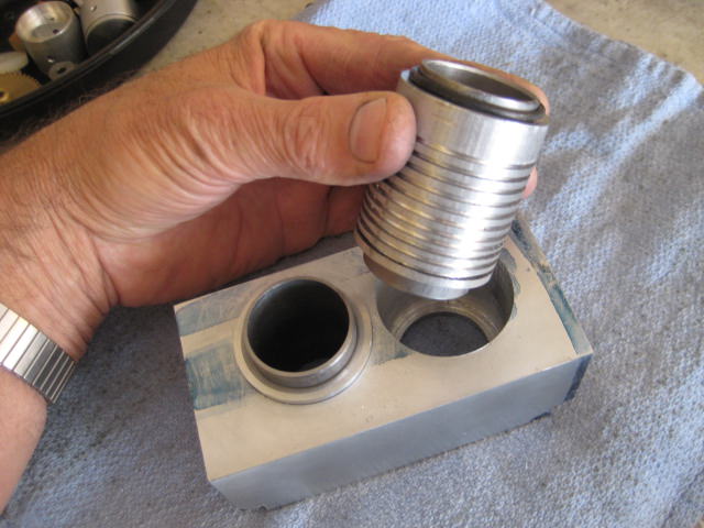
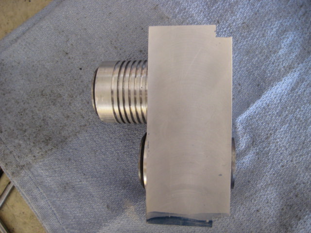
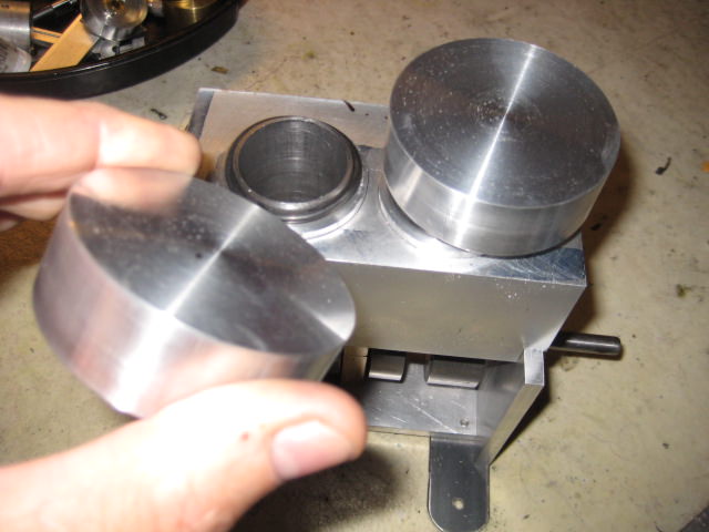
I have one engine with round heads. Now's the time again! Over at Industrial Metal Sales, they have bins of pre -cut aluminum and steel rounds. These 2x .75in. rounds are ideal for Stirling flywheels now drawn in to serve another purpose and engine.
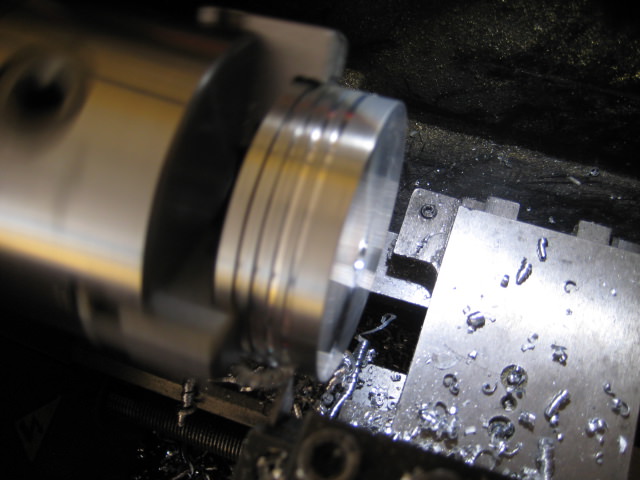
Some shallow cut fins introduced.
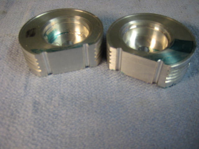
The combustion chambers are off set to match the block bore and I will need them deep. They are milled away for a butt fit over the 2 inch bore centerline and six bolts join them to the block then.
A relief spot cut in for a washer at the joint for some 6-32 bolts. No washers for the outboard fasteners.
The deep combustion chambers fit the brass valve guides in this position. The valves are canted from each other so the valve can be pulled from their guides in service without contacting the valve or guide on the other side. In BREEZE, the chamber is wide enough if the valves were in line. Since this is new territory, I didn't want to drill head for guides in line and find out the valves couldn't be withdrawn. :wall: This would be more important to note with smaller diameter chamber or longer stems.:thumbup:
The tapper ring around the chamber is the seat for the o-ring head gasket. This seal method is totally fool proof as the o-ring slips over the cylinder liner and below the liner seat machined into combustion chamber and is only marginally exposed to combustion pressures. The ports will be determined for int & ex plumbing and drilled at a later time then.
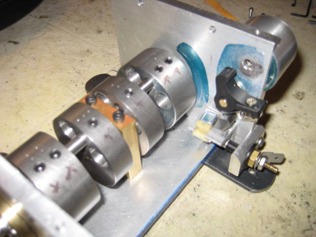
The lifter bar sits on top of the end plate overhangs adjacent to the engine block. A diagonal milling was made where the lifters and the body of the distributor would be on the bar. This was to give clearance for the distributor cap from the block and to gain mechanical advantage pivoting the rocker arms.
This set up didn't work as when putting on the dis. cap, the spark plug terminals were too close to the rocker arms. The diagonal between the lifters was milled away and a bracket with a greater angle for the distributor body was made and bolted to the lifter bar bringing the cap out and away from rockers then.
The distributor is driven by a pair of 24T, 0.5 modulus bevel gears below the lifter bar by the camshaft.
A PVC end cap 3/4 in. I.D. , some # 8 brass screws and nuts and a 3/16 in. CR shaft with a Delrin rotor ride in a brass bushing on this stubby unit. Some cap lock screws @ 90 degs. to be added to hold the cap to the distributor body.
The brass rockers transmit the cam lift to the valves at about a 115 deg. angle. Some 1/2 in. flame colored square steel tubing anchor the rocker pivots to the side of the engine block. A 10-32 set screw rides upon the lifter for valve lash. Use blue Loctite here. :thumbup:
I was going to use my last gear timing set for this engine but my idler gear could not bridge the gap between drive and driven. Saved for another time then. MXL cogs my favorite cam drive. We'll add a small idler wheel to take up the slack.
For the spark control, it's nice to know that I have two choices here. 1.) Tecumseh engine points/ condenser or 2.) Don't build any engines.
I did put the points cam, in brass, upon the camshaft instead of crank. It is easier access with a allen wrench to rotate cam for timing.
I found a vendor that sells C.I. by the inch. this will be a first cast iron flywheel for me at 3 1/4 in. diameter. A taper lock is used to mount to crankshaft.
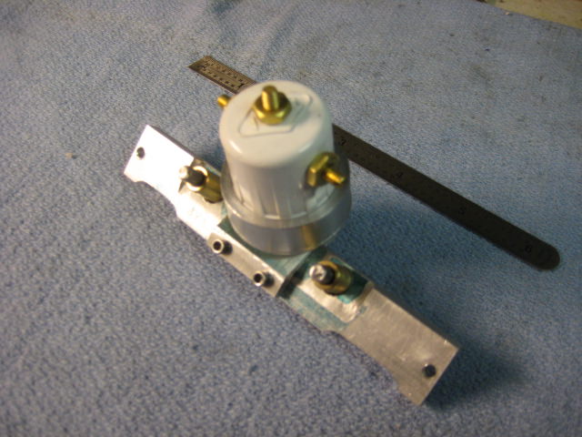
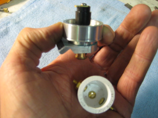
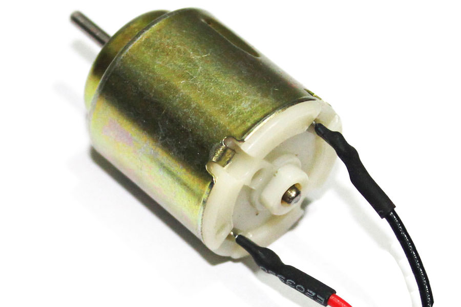
BREEZE will need a power supply for an accessory! I look through Amazon, Ebay and other online retailers. What I am looking for is a DC hobby motor. I want one that puts out about 6- 9 Volts at the lowest RPM, around 5- 7 thousand RPM as driven.
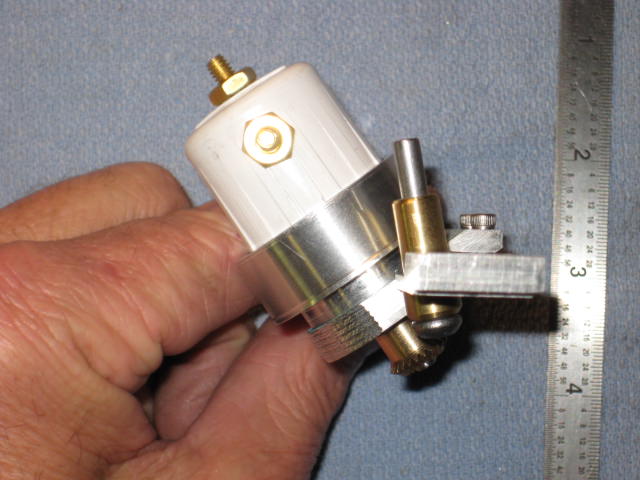
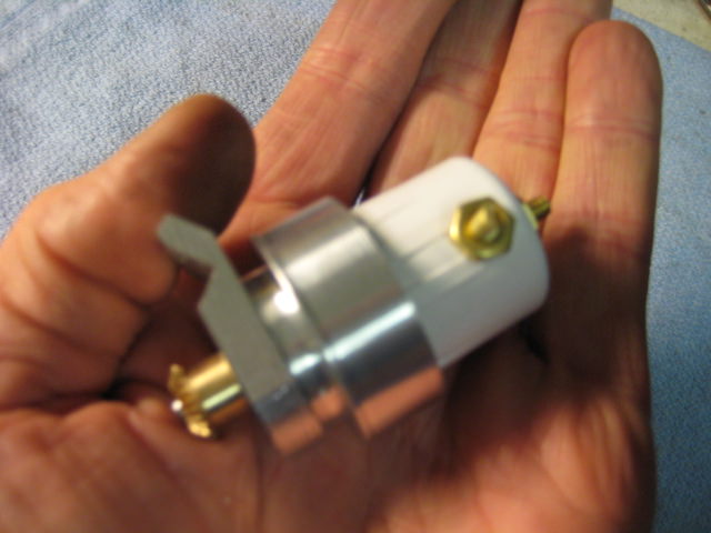
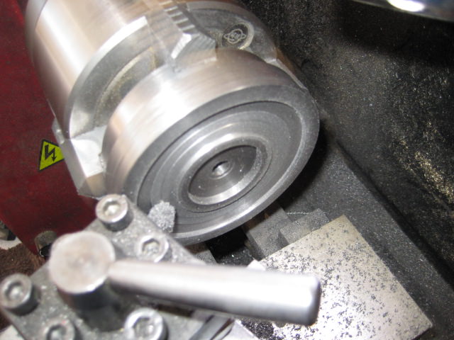
The low RPM motors tend to be fat bodied, around 1.25 to 1.375 inch cans. I put a rubber band around my 3 inch chuck and make some Delrin pulleys around 3/8 diameter push them onto the shaft and spin them on the lath to the idle RPM of my engine, around 1200. Recording with the multi meter the voltage output.
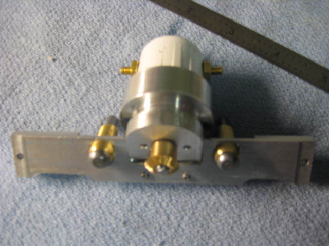
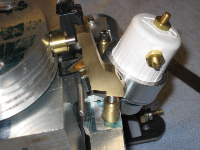
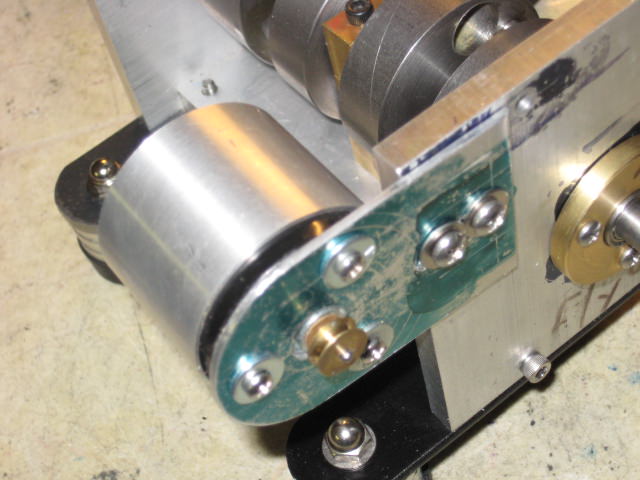
The motor slips into some aluminum tubing and some hardware store aluminum makes a handy mount bracket.
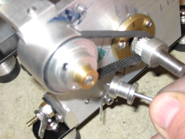
I get 7-8 Volts output at the designated idle speed for my accessory. An aluminum drive pulley is bolted to the back of the flywheel and rubber bands seem to work fine here!
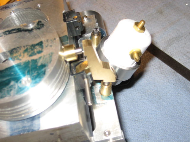
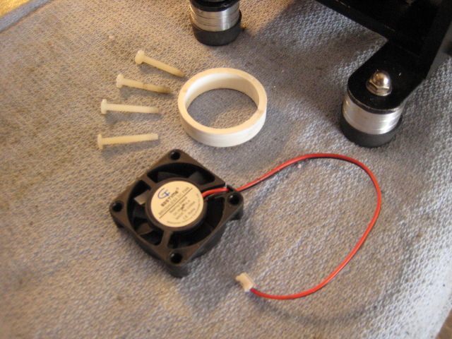
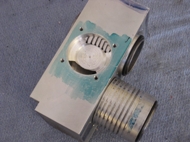
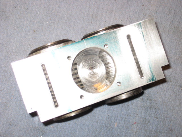
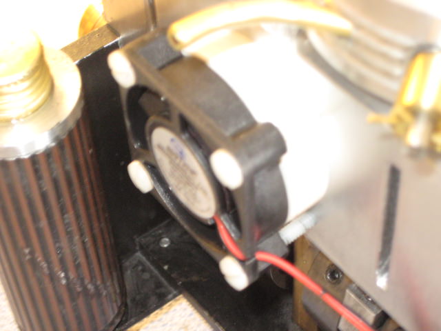
At the other end of the generator is a 40mm case fan mounted to the side of the block. It is heat isolated with a PVC spacer and nylon screws. This size blows around 9 CFM so it will be a gentle breeze around the radiators.
Adjacent to the fan are two vertical intake slots completing the airflow stream.
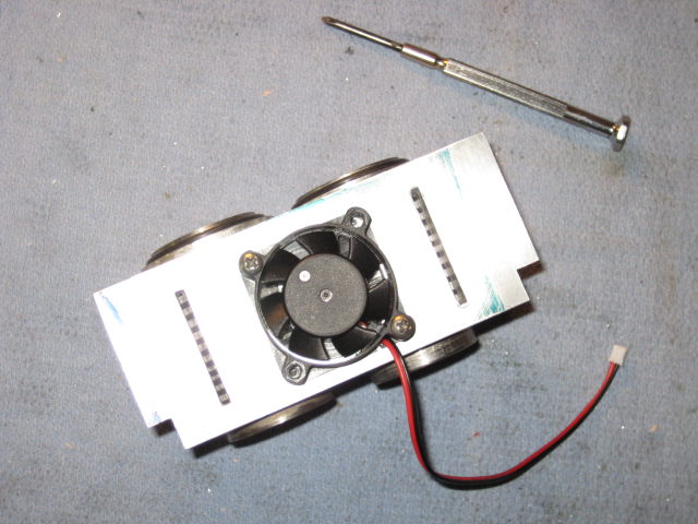
A 50mm fan would have just fit on the 2 in. tall block for more CFM flow. This 40mm job does all right.
Here shown with the plastic heat isolators. Fan set up runs as an exhaust but will run either direction. Engine at 1300RPM ,the fan spins near 6000RPM.
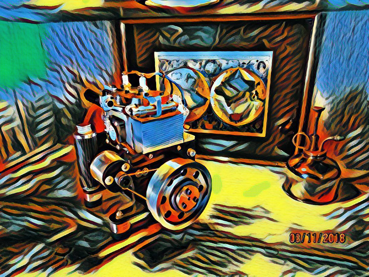
INTERNAL BREEZE is completed with the carb and mufflers now. Beauty photos and closeups to follow as well as sum "Hollywood"!Thm: