Longboy's "BEST FRIEND FOUR" model gas engine.

Home Model Engine Machinist Forum

Help Support Home Model Engine Machinist Forum:

This site may earn a commission from merchant affiliate links, including eBay, Amazon, and others.

Longboy

Well-Known Member
HMEM Supporting Member
Joined
Nov 19, 2009
Messages
806
Reaction score
535
Location
Tucson, AZ
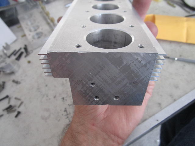
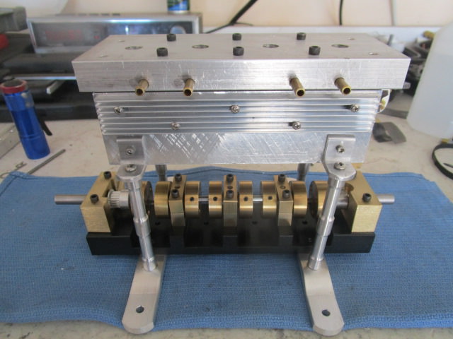
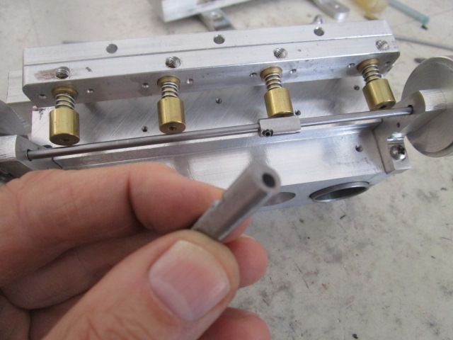
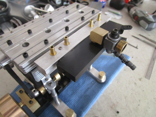
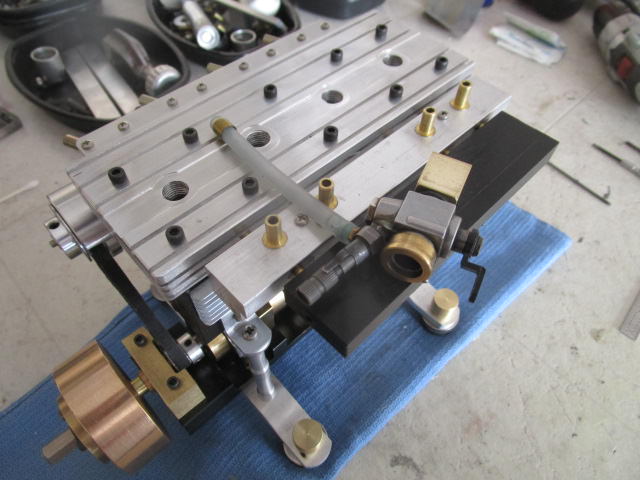
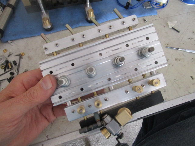
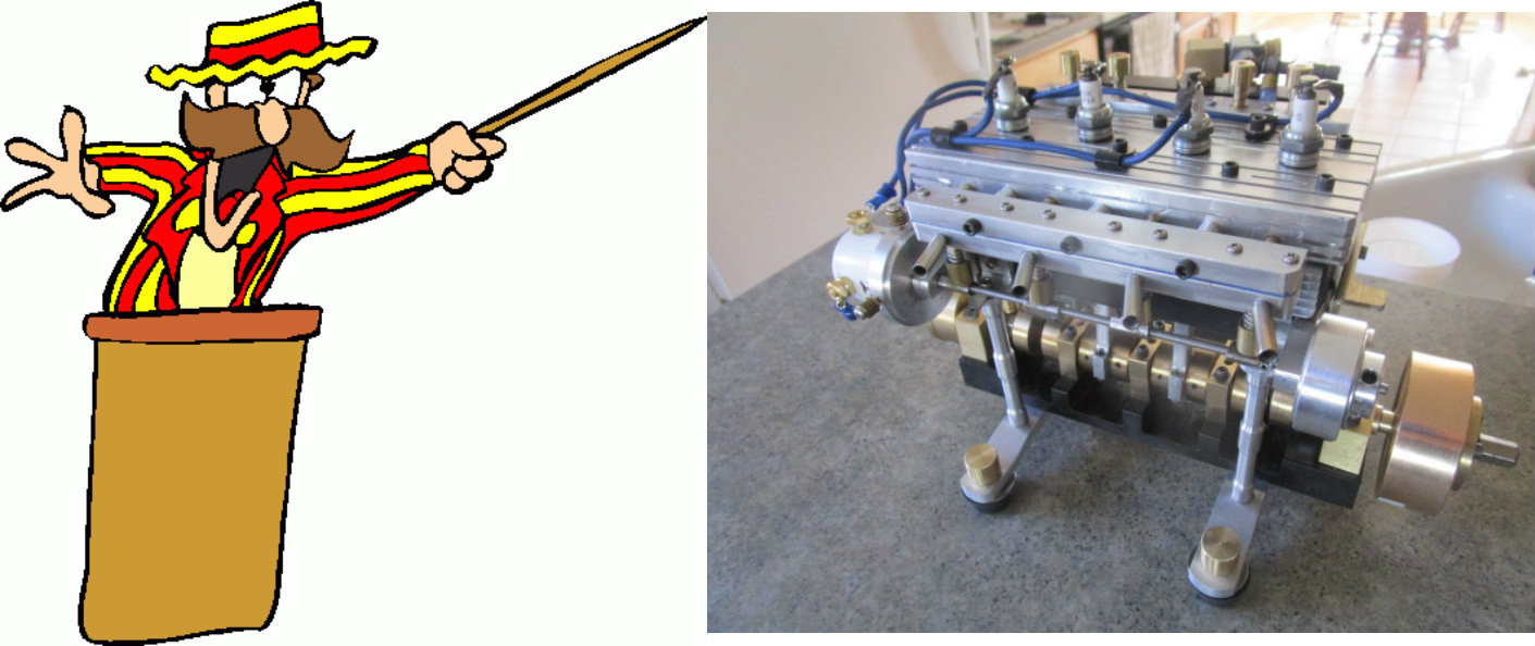
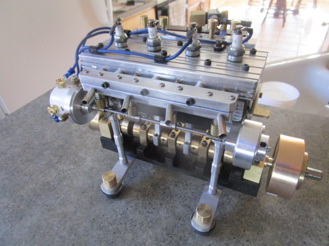
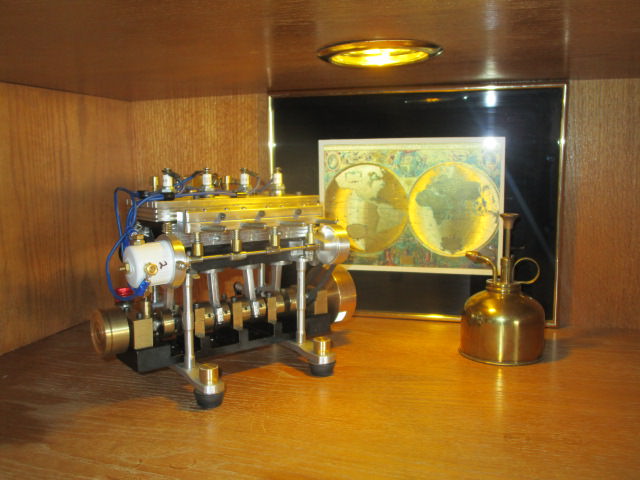
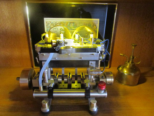
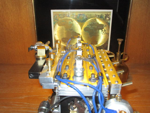
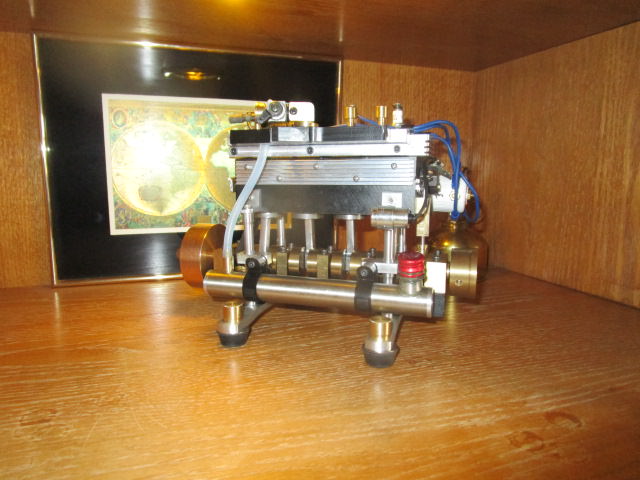
Flathead engines, an old design from the onset of internal combustion. Most notable characteristic is its cylinder head with nothing more than the spark plugs rising up from its surface. No camshaft or rocker arm assembly on top, its low profile stance calls attention to its named type. Valves in block along side the cylinders furnish the breathing.....except in this example! :)-\ ...where did you put those valves Longboy?)

The Best Friend Four story starts this weekend.

IMG_3112.JPG
 
The following photo is a crankshaft cradle made by "Parksy". Where he developed this for a steam engine, I thought on a future project this could be a basis for my next I/C engine and change my current 4 plate frame-up to a gantry or post support of engine over this cradle.

OqDd29j.jpg


My copy of this crankshaft cradle.

mT64mSF.jpg


The cradle is 2 in. width. The webs are 1-1/8 in. dia.

unhdeFu.jpg


In Satin Black.

EE4BkB1.jpg
 
Last edited:
The crank cradle supported by a pair of S- bend raised cross beams with the block to be mounted on four 3/8 in. posts attached to angle aluminum motor mounts from the side of engine block down to the beams.

MTuio0n.jpg


Block to have a set of 1.125in. OD -.062wall DOM liners for aluminum pistons.

im9Ye33.jpg
 
With a billet piece of aluminum for the block I get to use my new boring head on this project. I'll be using 1/4 in.width bar stock for the connecting rods here which allow me to reduce the bore centers to 1-1/2 in. This is a half inch less than my FOREMAN engine where I used longer webs and 3/8 in.width con rod stock.

XvJeLQ9.jpg


I bore the cylinders with the block bottom upright in the mill to accept the liners at a finger press fit and overbore here about 1/4 deep for a film of epoxy to bond in the liner with the block to the correct position later when the combustion chamber is bored into the cyl. head. The epoxy at the bottom of the cylinder is far enough away from the head where engine heat would not soften up the bond.

75iHWmM.jpg
 
The Chinese special boring bar makes a tapered groove around the cylinders for the O-rings that seal the cyl. head to block.

QC77RHe.jpg


What looks like the beginnings of a water cooled engine was not to be. The mini mill doesn't allow a 6 inch long block to fit under a boring head for making the water jackets. BEST FRIEND will be air cooled!

iViD782.jpg


Some finning can be machined into the block for ambient heat rejection....but I will be using "cladding" here instead! :eek:
 
Last edited:
Trying something different here. On Ebay, you can find heat sink material in various sizes. Always in hardware store grade aluminum, it is easy to cut and shape.

VXnzWcw.jpg


Choosing some 3-48 SS screws to bolt to the block, they can also be bonded in place.

zkbEWoT.jpg


There is room for another row between the motor mounts if needed. The same can be used for cooling cylinder heads. These are nominal 3/4 in. wide, 7 fins 3/16 in. tall but listed in mm. sizes.

uB2xSkp.jpg
 
The single piece cylinder head combustion chambers are bored 1/4 in. deep. The 10 mm. spark plug holes for CM-6 plugs are upright center.

H0U9zlm.jpg


Four head bolts per cylinder and intake/ exhaust cross flow porting drilled into head. Later the head will be decorated with some contouring /finning.

nItlClR.jpg


The liners are placed into block with their O-rings and then the head is mounted and torqued down. The liner bottoms out at the roof of head chamber and a reference mark is made where the liner is to be epoxied in the block with about .020 clearance from the chamber roof. Through the head porting. the liners are through drilled into combustion chamber.

pAe8q64.jpg


:eek: A concern of mine is the clearance of the exhaust port to the O-ring. I may need this modification shown on a test piece later. The porting is low on the head and the hot gases may deteriorate the O-ring. The solution is to have a tube extension in the head port passing into liner to bridge this gap. The liner hole is opened up to the top so the head can be dropped onto the block with the tube protrusion. The hole can be ground carefully through while in the block. :thumbup:
 
Looking good longboy. Will be following this build.

Oh and you have no idea how much it pleases me that someone is using my idea.:)
 
Points ignition working well for me and so equipped is BEST FRIEND. A change here to Kohler engine points. "Brian Rupnow" found these pushrod actuated points.....I'd thought I would try them out. Mounted to the front of the block they are crankshaft triggered.

wPrSReC.jpg


The elephant faced brass piece is the pushrod guide. A tiny steel barrel sits on the rod against the points rub block and a brass barrel rides the points cam on crankshaft. The condenser ended up under one of the screws on the end bearing block.

oldqPj6.jpg


I find the Kohler points has an extraordinary stiff spring for a model engine. On the points cam, I radiused the ends of the milled in flats and sphered the bottom of the brass barrel for a softer ride over on cam. Some lube grease and engine run in makes the operation smooth now.:)
 
The very basic barrel piston and a plain shape connecting rod fabbed from 1/4x 3/4 aluminum bar. I don't find Viton O- rings in my size at Ace Hardware. A plumbers O-ring made from....black stretchy stuff, makes the seal.

nEQDgXH.jpg


A pair of R144ZZ bearings ride in the small end. In a tutorial by "Brian Rupnow", he mentions aluminum con rods can be their own bearing riding on the crankshaft throws. This would allow narrower bar stock to be used. BEST FRIEND uses 3/16 in. throw pins and the 3/4 in. wide stock can run on 1/4 in. pins using 4-40 rod cap bolts.:thumbup:
 
On each side of the cylinder head will be the valve blocks mounted in outrigger fashion. On the ex. side, a strip of painters tape on each block face, some RTV sealant and eight ss 3-48 screws hold it together. After about 3-4 tries, it was leakage free. The exhaust block is 9/16 in. wide and the valve guides are 3/8 in. it was difficult putting on the RTV around the guide without contaminating the valve head or guide face tightening the screws down.

JOl2cuc.jpg


On the intake side, I tried furnace tape on the faces.....it was too thin. I went to some .060 gasket paper with RTV.......still leaks. The gasket paper would get saturated with fuel and on compression stroke, would foam out between the two pieces! Not much margin here either from valve guide to edge of bar stock....and the screws are tightened. :confused: Would have to find sheet rubber gasketing, remake using wider bar stock.....or sum-tin else.:(

KZjgHAb.jpg
 
The valves are stainless and the block has enough room for my solution.

viyL6ul.jpg


yZYMM7k.jpg


Some 1/2 x 3/8 in. O-rings have enough support on the block.:thumbup:

fnAToln.jpg


nEFbbKw.jpg


The guides were removed and a seat was cut in around the guides for the O-rings. This is a leak free valve block now!:)
 
Another area that has to be leak free is the porting between the cyl. head and valve block. The brass tubing is blue Locktite in head but I want the valve blocks removable from head.

ukR8BYs.jpg


A set of eight collars for both valve blocks were made with O-rings to slip over the tubes. Three 6-32 bolts draw the blocks up to the head against the collars for the seal. The tubes do not penetrate the valve block port too deeply, the valve guides are close to the edge of block.

A side note with this valve arrangement is the porting volume, from cylinder to valves, becomes part of the combustion chamber volume for figuring the compression ratio. In BEST FRIEND, that would be 2 inches of 3/16 in. diameter porting between cylinder and valve guide per cylinder or .901cc.......ah, forget it!:D
 
The cam drive is a pair of 25/50 MXL sprockets. There are tooth belt calculators to determine the number of teeth needed for your set-up. I use this one!
http://www.bbman.com/belt-length-calculator/

LWrdsBZ.jpg


The cams just keep getting smaller! I'm using a 1/8 in. ss shafting with 5/16 in. cr lobes. This is the smallest I can manage for cam making stock. Easy to hand file the profile after a couple passes under the mill creating the ramps. 4-40 set screws lock the lobes to shaft. The lobe shows around .085 in. lift.

Q1EDt23.jpg


The bucket lifters are threaded to the valve stems and evened out to same level. Valve lash is covered then by moving the camshaft up to the lobes, the mounting brackets for cam are slotted.
Initially the shaft would flex on valve spring compression, the span between bearings is over 5 inches. The ex. valve springs here were rewound using .020 piano wire to eliminate that issue, the .025 wire used too stiff. Another solution would be an added center shaft bearing.......but the Budget Dept. memo'ed back that there was no funding for that.:eek:

A distributor cap base and sprocket guard are mounted to the camshaft brackets using a pair of 3-48 ss screws.

zTYTOnt.jpg


pzDSUMP.jpg
 
Last edited:
A candy bar's worth of Delrin becomes the intake tract for BEST FRIEND. Is the best material here since mankind crushed rocks to make aluminum!:thumbup:

RAsN5sr.jpg


A 1/8 in. brass modified plumbing elbow mounts the OS carb on top of pendulum. I really didn't care for the carb right angle stick-out. What to do.:(

NRMZmLL.jpg


Turning the carb 90 degrees and swinging it over the intake gives a cleaner look. The fuel metering screw now over the its top and the fuel line tucks in between the valve block and intake.:)

yHgunAG.jpg


The finalized intake was trimmed to width then. It is just a thumb press fit over the valve block port tubing.


K1q2qOw.jpg


The exhaust pipes come into the ex. valve block at an angle. I want to assure the forum that only the best quality steel shafting..... ever to be found in a Korean made VCR..... was used in their development!:D

JOl2cuc.jpg


This is BEST FRIEND FOUR'S story. Coming next is the studio photos and the running presentation!:eek: .... See you there. :) Dave.
 
Welcome to my presentation of the BEST FRIEND FOUR flathead engine.:)

wjY4VvP.jpg


X1U21pl.jpg


The block and cylinder head were started back in July.

IpKMDjW.jpg


7Yu8r0p.jpg


Work was set aside for the cooler days of October then.

ZHxJ146.jpg


Early February to completion.:thumbup:

sHcgFFN.jpg


Being different with the outrigger valve blocks.:eek:

jH1eW9b.jpg


And repurposing electronics items for engine radiators:idea:

H1n7K7Z.jpg


And now.....in today's experiment, see how to burn a bottle of Coleman Camp Fuel in 4 easy cylinders!:D
Thanks for coming by! Dave

[ame]https://www.youtube.com/watch?v=2bRFujsk8LU[/ame]
 

Latest posts

Back
Top