Live Steam Loco build - Bulleid Light Pacific

Home Model Engine Machinist Forum

Help Support Home Model Engine Machinist Forum:

This site may earn a commission from merchant affiliate links, including eBay, Amazon, and others.

syrtismajor

Junior Member
Joined
Feb 15, 2010
Messages
50
Reaction score
21
Hello all,
I may be a little transient on these boards but I am hoping to change all that with this thread.
If you know me on here, I was attempting to build L.B.S.C's 'Virginia' at 1/16 scale (3.5" gauge). While this engine was challenging and enjoyable, it wasn't the engine I actually wanted to build. Now I've had some scares recently including being diagnosed with epilepsy (there is a thread about this in the disability section), I've decided to shelve it for the foreseeable.

Since I am from the UK, I wanted to build an engine of that heritage. I didn't want to build a 5" or a 7.1/4" gauge as they are huge and I have limited room to build/store it. The real challenge however was trying to find plans for a loco I actually wanted rather than a 'sort of do'. I was tempted with the 'Heilan Lassie' that was also designed by L.B.S.C but that seemed a little ungainly in appearance (I'm not a fan of Thompson's re-builds but that is another story that I recommend you hunt out and read).

Anyway, I'm drifting from the point.

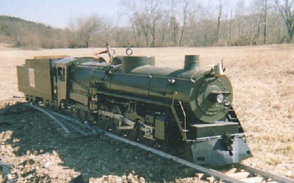
I wanted a large loco with power, and one that you don't see that often. I also wanted one that I could design myself rather than altering existing plans. Since I also love O.V.S Bulleid (http://en.wikipedia.org/wiki/Bulleid) and his innovative locos, it just had to be one of his marvellous Light Pacific's.


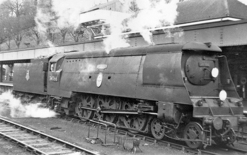
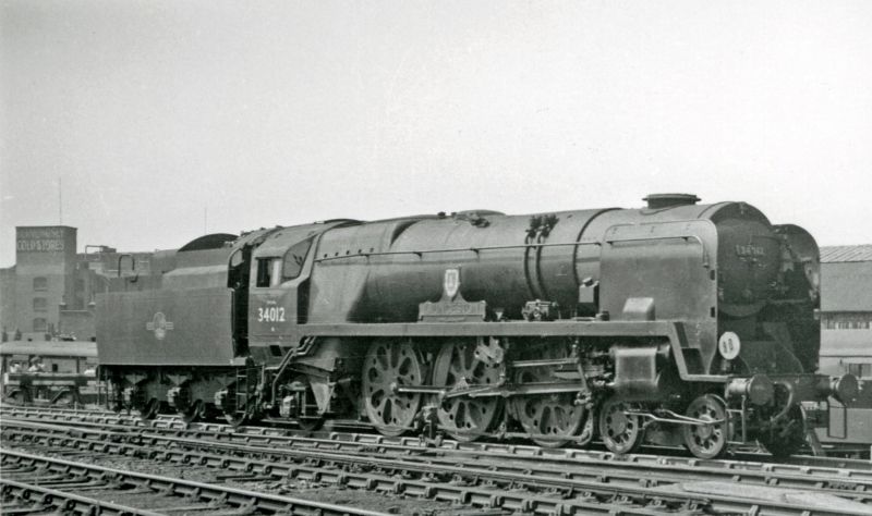
While I think that class is lovely, it doesn't 'look' like a loco. This means that I probably controversially went with one of the rebuilds:


The main catch is that there are no plans that exist for this engine, that is the challenging bit ;)
Now to show that I am serious, here are the first blanks to be on the production line...
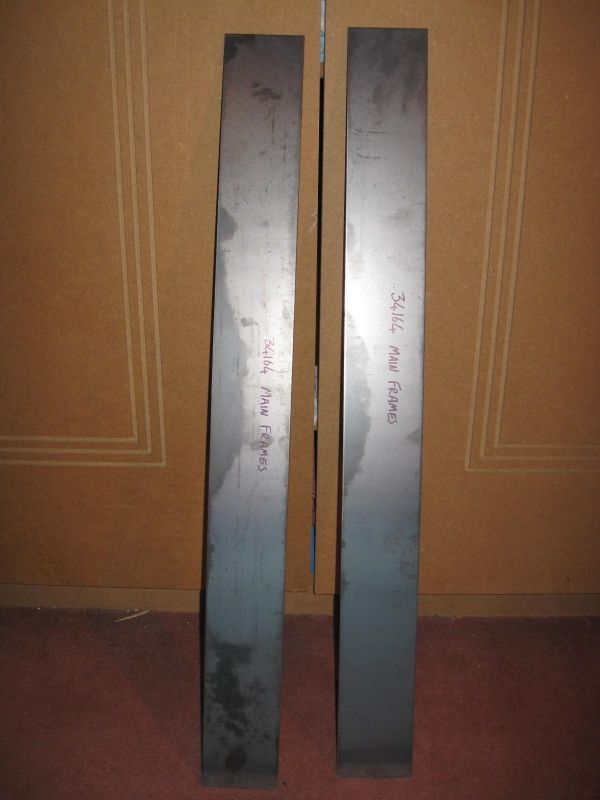


The frames!

I'm hoping to update this every weekend... let's hope I will :D
 
The first week has passed and I am making another post. Hopefully I can keep this up ;)
Last week I showed the raw steel plates that would form the main frames of the engine. I thought that because they are the heart of any loco and that they should form the 'canvas' for me to work on.
I've heard it said that steel plate frames are a pain to create, this I can agree with. The last frames I handled (for Virginia) were laser cut from 1/4" steel and I am glad I took that option! I could have gone for laser cut here but there are no commercial drawings for a 3/4 scale Bulleid Pacific. I had to sketch my plans out on a roll of paper (difficult to scan in) and didn't have a clue on how to transfer it into any form of CAD/CAM thingy. That would also take a long while and I still preferred working things out myself. I must admit however that it was fun scanning through various drawings and reading quite a few books to get them as 'operationally' accurate as possible (true to life but with compromises, I am not a rivet counter :D).
The only image I do have as an electric copy is the overall layout drawing I finished about three years ago:


It may look a little fuzzy but that's because it's pencil and taken with a camera in low light (the flash dissolved it into glare!).
Anyway, after a good few days with a hacksaw, milling machine, files and a few choice expletives I had my 1/8th thick and (just over) 24" long main frames:


They're still technically 'raw' as they have not had the last bit of the tops filed and no operational or pilot holes drilled but the overall shape is correct. The only main items missing are the rear frames. These however will be the next challenge.
Hopefully I'll be back in a week!
 
Looks like a real good start. I wouldn't even know where to begin with something like this. Keep the pictures coming and thanks for sharing your progress.

Many thanks stevehuckss396! The main challenge for me is translating the existing engine into an operational model. It was for this reason that I have taken any opportunity to take as many photos as possible of any of these Pacific's whether operational or under restoration. There is also a wealth of information on the internet or various voluntary organisations who dedicate their time to ensure that these loco's are still operational today. It is to these people that I bow my head to.

Anyway, on to todays update...

Last week I stated that the rear frames were my next challenge. The prototypes has a long 'swan neck' shape to clear the firebox. This however posed a problem since they would be rather narrow and would have the tendency to bend with the weight of the train it was pulling. This in turn would lead to fatigue and potential breakage. Thankfully Bulleid was aware of this and designed in a feature to prevent this from occurring. He simply designed the frames to be in one length of steel but 'doubled up' the thickness at the swan neck area. This can be seen in the following photos (taken from 34105 'Swanage' at the Mid Hants Railway):


These were both taken from the rear of the locomotive looking forward to the rear axle. You can clearly see the thickness of the frames nearly doubling to prevent fatigue in this area.

To me this was a little troublesome in that it decreases the area between the rear trailing wheels and the frames. While this worked in practice it meant that my engine wouldn't be able to tackle the occasional tighter curves found at many 3.5" track layouts as the wheels would foul the frames. Rather than just plough ahead regardless I solved this issue early in the design stage.

The plan was to use 3/16 thick steel plate fixed to the 1/8 thick steel frames. These would be fixed to the inside of the main frames to give a much larger clearance for side swing of the rear trailing wheels. Where they were to be attached I would mill out a 1/16 recess. The final assembly will then have a sturdy frame stretcher to add further strength to the area (this will be later in the build however). Here is a photo to hopefully make this clearer:


The roughness on the milled areas look far worse than it actually is!
To give you an idea of how these fit with the main frames, a picture says a thousand words:


The frames when completed will now reach the designed 31 inches in length. I think now I may tackle some of the stretchers although I will not be able to assemble them until I can afford a TIG welder...
 
Me again!
After all the fuss with the frames I wanted to step a way for a short while and tackle something a little easier to work with. I thought that a little brass would suffice to make the buffer stocks.

In total there were 110(!) locomotives constructed between May 1945 and January 1951. This obviously meant that there would be design differences between them all. While a few on the originals were obvious (cab design is a good example) there were a few more subtle differences. One of these were the buffers... :wall:
To demonstrate here are two pictures from the same class:

34053 'Sir Keith Park' under restoration at the Swanage Railway:


34067 'Tangmere' on a mainline tour at Weymouth station:


Since my loco isn't a model of a distinct engine I have decided on the dual thickness style as seen on 34053, just because I prefer the look of them ;D

Firstly I got some brass bar stock cut into the rough lengths (I swear that the hair is from one of my four cats!):


These were the drilled through and reamed out to 3/8th:


The final stage using the four-jaw to ensure that each ends were lined up accurately, was to turn the outside to shape:


While simple, these gave me quite a buzz of satisfaction after the long slug through the frames. At some point I'm going to manufacture the shafts and faces of the buffers. Before that however I am awaiting the delivery of some 3/16th steel rod for the springs to coil around ;)

Until next time, have a good week!
 
Wow! Quite the project! Your parts look great! I also think that's a pretty fine drawing
you've created for this. Keep up the great work!

John
 
Wow! Quite the project! Your parts look great! I also think that's a pretty fine drawing
you've created for this. Keep up the great work!

John

Once again; thank you very much for the kind words :). I shall endeavour to keep up the progress and this thread...

Speaking of which I only have a short entry this week as other things have taken priority. This will however show some progress on the buffers.

Since the main stocks have been made up I thought I would make their complementary mounting plates. These should be about 3/32 thick to be within scale. For this I cut four squares out of 1/8 brass flat bar:


(I swear I'm going to have to shave my cats!)
These were then carefully mounted into the four jaw to trim them down to the required thickness and leave a small locating spigot for the main stocks. The main stocks were then tested for fit:


That was as far as I got. They still need to have the edges rounded off and fixing holes drilled (I think for M10 or M12 bolts should do). The next task is to definitely make the main shafts and faces, hopefully in a weeks time :eek:

Until next time, keep machining
 
I'm really going to enjoy this thread! Thanks for sharing.

I was never really a train person - but the company I work for now does a lot of work in rail and I've started to get the bug!
 
Whoops, I seem to be a day late with this update. I've been tied up with DIY and what not.

Thanks again for your replies, they're keeping me motivated to carry on ;D

Since last week was a bit anaemic I thought this one would be a bit heftier to make up for it. As the previous two updates I am still working on the buffers. This time I am now tackling the shafts that will slide into the stocks.
Firstly I had to turn some 3/8th steel into the following blanks:


These all then had a small hole drilled in one end:


Since my 3/16th steel arrived I was able to make a start on the spindles that will form the supports for the springs. These were turned as such:


The base plates then had a 3/16th hole drilled through the centres:


While all of this may seem a little hard to follow, the following image shows how it all comes together:


The short turned end of the spindle is a push fit into the holes in the shafts (to be silver soldered later). That assembly is then fed into the stocks with the spindle passing through the hole in the base plates.
The long turned part of the spindle will be threaded to 5BA to take a washer and nut to hold the whole shaft thing together.
The un-turned part of the spindle will hold the (still to be wound) spring that will be held under slight tension. All that will need to be made after that are the buffer faces! Although I'm still not quite sure how to tackle those...:confused:

Hopefully be here again next Sunday! Until then, Ta-rah!
 
Okay, I'll try this again and hopefully my browser will not crash out and make me lose the whole post that I am about to write again. :(

Anyway, the next challenge was the buffer faces. These (to my mind) are inherently tricky as they need two convex faces on one steel plate. I have never done anything like this before and so took the following path...

Firstly I cut a blank from a length of 1" BMS bar (I assume it is BMS as it is the same colour etc. as the other pieces not in my 'useful box of bits'):


This was then faced off in a three-jaw and a 3/8" cavity bored into it to accept the end of one of the pre-manufactured shafts. The blank was then turned around that cavity to form the shape of the rear of the buffer face:


It all seemed to be going well so far...

To be able to turn the facing side of the buffer I had to assemble the other parts together (the shaft and spindle) and give them a dose of heat and silver solder. This is what came out of the pickle after a bit of a polish:


Now I had a secure point to hold in the lathe, I carefully took more and more of the steel off in thin layers until I had a rough shape similar to the rear side. A file was then used to 'smooth off' the turning ridges followed by gradually finer grades of emery paper until it looked quite well polished.

Then this is what it looked like:


woohoo1

I just had to assemble it to the other bits to see it 'in situ':


To follow on from that I just had to make the other three:


Huzzah! Any further work on them can wait now until they are needed to be fitted.. a littler further in the future of course!

Right, what next? :)
 
I forgot last week was Easter... whoops...
Anyway I have actually been working on the engine although I have moved on from the buffers as they are practically ready for solder assembly. Since I enjoyed all the turning I thought I would carry on down a similar route and start work on the cylinders.

Firstly I would like to take this quick opportunity to say how I do not like working with castings. This is most likely due to my inability to securely fasten them to a lathe or mill without the possibility of chatter and breaking a tool. I have also had a couple of bad experiences of castings having bubbles in just the wrong place or being slightly to small in vital areas. Whether this is just down to bad luck I'm not sure but it does mean that I am more likely to fabricate if possible. This (in my mind) also prevents the chance of a whole component being irrevocably damaged near completion (normally resulting in some new expletives and a slightly smaller bank balance). It also allows me to build each piece individually before assembly.

A while ago (maybe even a year) I asked on this forum about fabricating cylinders from brass and gunmetal. The overwhelming response was to machine from cast iron but straight away this would mean a shed load of machining from bar. A friendly fellow engineer on here however pointed me to a company that sells hollow gunmetal (hurrah!) that I quickly bought a foot of. This metal was then cut into three 'chunks' that would form the three cylinders of the loco:


Expensive blanks of LG2 metal!

I made a slight error here that could of saved me some cash. It all could have been remedied by a little research. Instead of ordering the diameter needed I ordered over size. Since I didn't know that they give between 3/16 and 1/8 over size anyway, I had had to machine away about 3/8.

Since the raw stock was technically a casting (extruded rather than sand cast) I had to ensure it would run true. This was quite simply down by turning one end in the three jaw before flipping round in the four. This gave me the following 'barrels':


Each barrel was then fully turned down to their required diameter (you may notice how much material was removed):


A lot of heavy and slightly pricey swarf was produced from that. I would say I learned my lesson but I ordered the material for the valve sleeves at the same time as well. The good news however is that I now have all three cylinders (sleeves?) machined to the right external diameter. What they need now are some 3/8 brass mounting brackets.

Tune in next week since they should have been started by then.. hopefully...
 
"The main catch is that there are no plans that exist for this engine, that is the challenging bit
wink.gif
"


I had none either, but did use a line drawing giving rudimentary overall dimensions. Chicago Burlington & Quincy Northern # 5632. Long story, ask for more if so inclined! 9 years, 8000 hours, I finally had this. I hear it's known as "scratch building". I DID scratch my head a lot! jack


img00511.jpg


Hmm, I have been away from this thread for a while. This isn't due to anything else other than my computer nearly exploding (well, requiring three reformats and a new Hard Drive) and my new bedroom being completed. This meant that my work bench has been under about a foot of items in temporary storage. My bench however is now clearer and ready for more engineering work.
But first:

"The main catch is that there are no plans that exist for this engine, that is the challenging bit
wink.gif
"


I had none either, but did use a line drawing giving rudimentary overall dimensions. Chicago Burlington & Quincy Northern # 5632. Long story, ask for more if so inclined! 9 years, 8000 hours, I finally had this. I hear it's known as "scratch building". I DID scratch my head a lot! jack


img00511.jpg


Crikey!
I am always impressed by people that can pull things like that out of their heads. I've heard if people using 'works diagrams' and scaling them down but that makes my head hurt. How did you go about building that?
I do have another question however regarding the wheels... Are they castings or fabricated?

The main reason I ask is that all of the Bulleid locos had very distinctive (in the UK at least) wheels in that they were a variation on the Boxpok design often used in other countries. These were known as 'BFB' (or Bulleid Firth Brown) wheels and were renown for being lighter and sturdier than standard spoke wheels.


I was tempted to fabricate my own but knew that it probably take me a year or two to complete, especially as there are six drivers, six leading / trailing and six tender wheels! :eek:

Because of this I was rather relieved (read elated) when I found out that there was one company in the world that does offer castings of those wheels:
http://www.ajreeves.com/miscellaneous-castings-286-c.asp
(they're the 'Merchant Navy' ones)

After spending nearly £300 (over $500!) I had a casting for each wheel:


This is only the driver (measuring about 4" in diameter) and as you can see, it is a little rust eaten. The others are much cleaner:


(Leading and trailing on the left, tender on the left)

Unfortunately they are not exactly accurate but I feel that they'll suffice. I also know that I am not a fan of castings but these will have to do, they have in the past been successfully used on other locos based of Bulleid's designs.

Anyway, since I haven't actually done any engineering this week, there will be some next Sunday ;)

Until then...
 
Another week, another post. This time it is a continuation of the cylinder manufacture.

As you saw from my last production post, I am fabricating rather than making do with a 'sort of right' casting or going through the hassle of getting a proper one cast. This also makes more sense to be as it will be easier to remove the valve chest if required.

The hefty brass bar was first cut into a series of blanks:


These were then roughly marked and drilled through. Following that they were mounted in the four-jaw and bore milled out:


My first video on here, yay! (Please excuse the shakiness)

A fair amount of time and a shovel or two of swarf resulted in this:


Is it me or does the bore look a little rough? Strange as it doesn't look that way without the camera flash :confused:

Anyway, the test fit on one of the barrels followed:


Success! ;D

Now just another five to go... :(

I better get a comfy chair and fire up the lathe for another hour or six...

Until then, enjoy your week!
 
Wow, this machining stuff takes a while doesn't it?

You remember that I mentioned the 'hefty bar' of brass? Well this was it before it fell to the hacksaws wrath:


I now think that about 50% or so of it is now shiny gold-like swarf after all the holes were bored out.

The two outer cylinders currently look like this:


Once they were complete I tackled the centre cylinder by pretty much the same way as the other two..

Blanks:


Holed:


Cylindered:


I've only got one last one to bore out and the rough cylinder blanks are complete. No further work will take place on them until they are silver soldered together. That will hopefully give me enough time to figure out how I am going to mount the valve chest to the centre cylinder. This is because it sits right underneath the smoke box and cannot protrude to far into it. To resolve this the valve was set to the right between the frame and the exterior of the cylinder. This places it in such a way that any bolts fixing the valve will have to be at an angle, unfortunately that is where the frames get in the way. If it all seems confusing I'll come back with a sketch.... In fact I think I will next week along with the explanation for all the '34164' numbers written on the metal and a proper reveal of what the loco's name will be ;)

See you soon!
 
Since the world has conspired against me over the past two weeks with the on going Seig Mill fiasco (although it seems to be fixed now), I haven't made much progress. Because of this I have overlooked a few things, notably the explanation of numbering etc... What I have been up to however is pondering over the rear (and largest) stretcher on the loco.

Now technically it isn't the last 'stretcher' as that is the drag box. This one is the box-like fabrication that holds the frames as rigid as possible prior to the firebox and where the rear frames meet the forward frames.

As you can imagine, this structure will be under a lot of stress in use and have no chance of failure. Since it is buried in a critical location it would be rather tricky to remove it without disassembling the entire loco.

I have posted a picture of it before, the picture taken from 'Swanage' which is currently under restoration:


The image was taken by leaning over the drag box and as you can see, it is quite a substantial component. You should also be able to see how hard it is to get a good image due to it's awkward location.

Thankfully however; fortune fell upon me this spring:


The rear stretcher removed (and painted a rather fetching shade of rust proofing pink). This view is from the exact opposite as the previous image. It is upside down and the forward side facing the camera. The two 'wings' are the spring hangers for the rear drivers and the small hole in the top middle is the pivot point for the rear bissel truck.

With that image as a reference I scratched my head a little to think of a simple(ish) way of achieving the same result.

My first idea was to simply use a section of standard box steel. This was quickly thwarted however by the need for a location for the spring hangers. I could still however use some box steel and modify it to work. With that in mind I spent a few £'s and got some 40x40mm box steel stuffed through my letterbox. I quickly got at it with a hacksaw before realising that I hadn't taken an image of it:


A short while later I had an expertly machined (roughly cut) 2.5" long piece of steel:


It will be from this that the whole stretcher will be built around. This will hopefully occur over the next two weeks (I say two as this time next week I'll be away on Holiday).

Until then, Ta-rah!
 

Latest posts

Back
Top