


Sshire
Well-Known Member
- Joined
- Jun 29, 2011
- Messages
- 936
- Reaction score
- 259
Liney RV-1 - A New Double Wide
Part 1
The way to succeed is to double your error rate.
Thomas J. Watson
Chairman and CEO of IBM
I had the plans for the RV-1 on the bench for a few months while I was working on the boiler. I was following Bill Lindseys build and didnt realize, until he finished it, that it was smaller than I had imagined. So, all dimensions times two seemed doable.
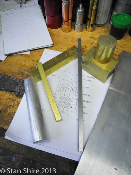
I printed a second set of the drawings and, with a calculator to check my math, wrote the new 2X dimensions on the plans.
I went through the brass and aluminum stores and ordered what I didnt have.
Most pieces laid out on the bench all ready for their weight reduction.
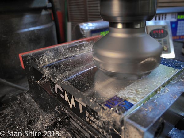
The base plate, a .375 6061 piece, becoming square.
The 2 face mill gives a beautiful surface.
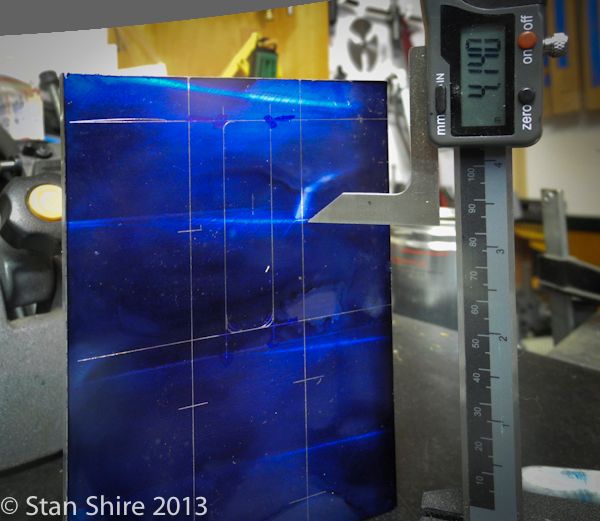
Even with the DRO, I feel better marking out the piece. That way, I have a better chance of catching a screwup before it happens.
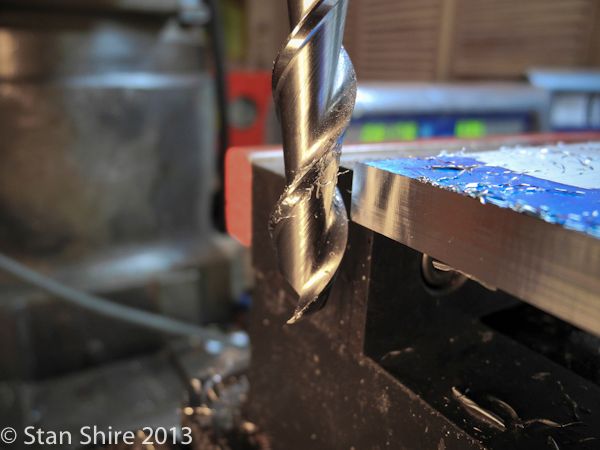
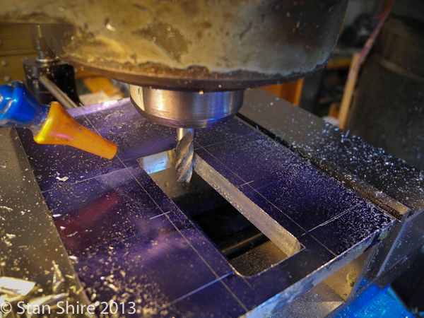
After finding the 0,0 corner and zeroing out the DRO, I plunged an end mill and began making the cutout for the flywheel. I changed to a smaller diameter end mill for the corners and finishing pass.
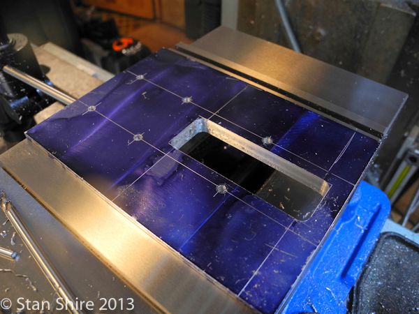
With the flywheel opening cut and mounting holes drilled, it was good to see that each hole was perfectly positioned on the scribe lines.
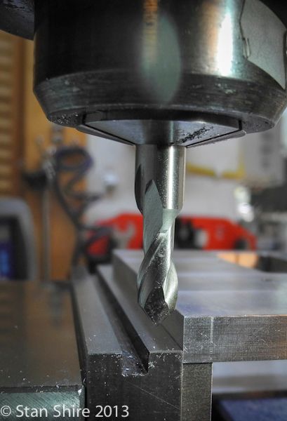
I like to mill a bevel on plates. Cutting the edge against the fixed vise jaw makes everything work nicely with the bevels all around matching at the corners. Cut, turn 90 degrees, cut, turn, etc.
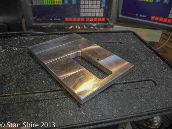
First part done. Of course, more sanding and polishing will come later.
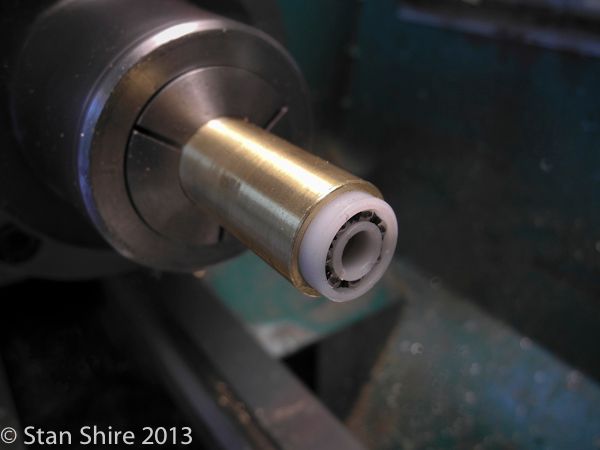
The flywheel bearing towers are next. I had seen these acetal bearings with stainless steel balls and though that this might be a good engine for a tryout. They are described as no lube if run under 2500 rpm. Maybe.
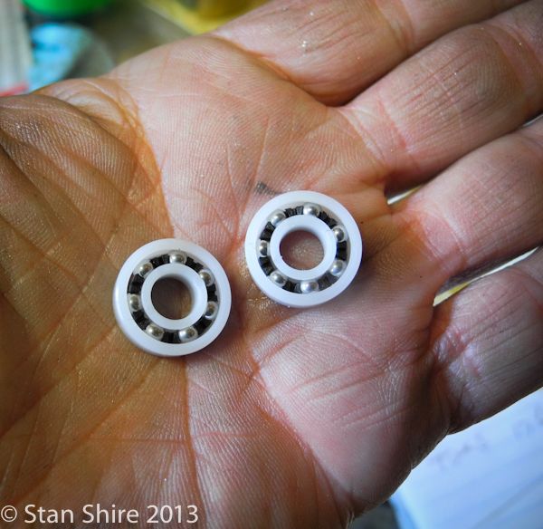
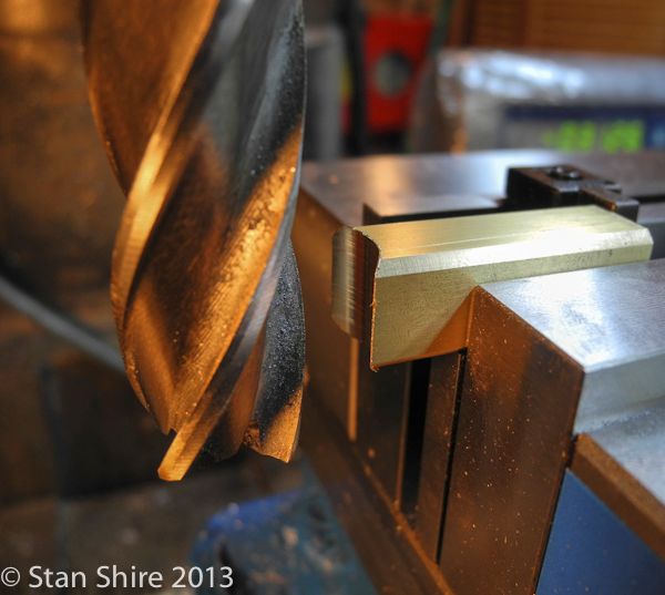
The primary problem is that they are wider than the .5 x .5 brass square. Even though there appears to be plenty of room for a wider piece, I had another idea. And Im not in love with straight square pieces.
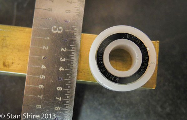
That looks like it might fit.
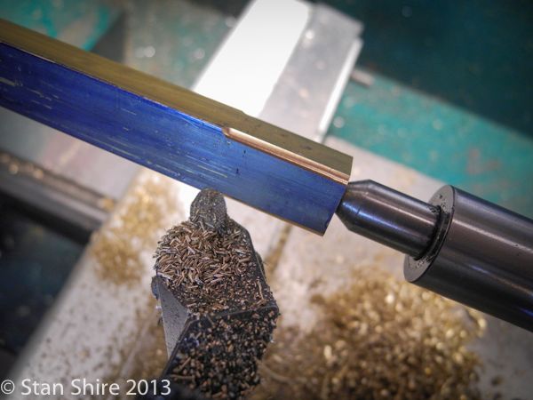
A bit of drilling and boring got me just under what I need. The engineering data for the acetal bearings gives from 0 to -.003 interference. The bearing O.D. is .625.
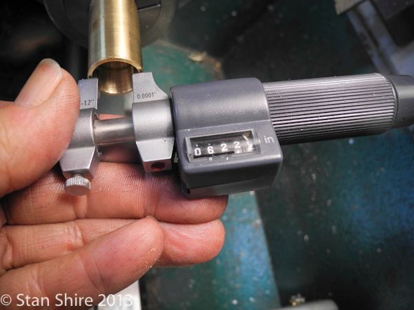
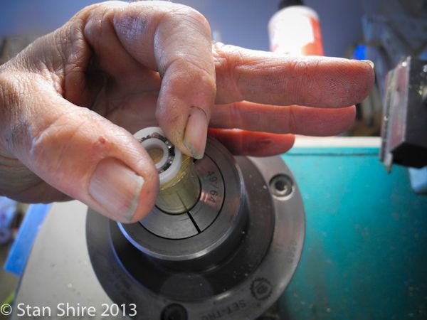
Im going to line bore the last 1 or 2 thou when the blocks are mounted on the baseplate. For now, the bearing almost presses in.
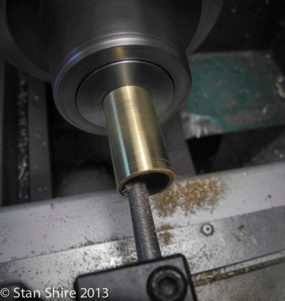
Good enough for now so I parted off two pieces.
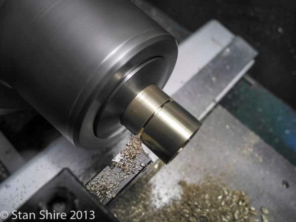
I wasnt overly concerned with the internal finish as that will go away when they are bored to size.
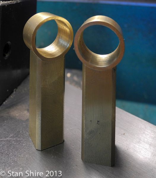
For the bottom of the bearing tower, I rounded off the corners of the .5 square bar.
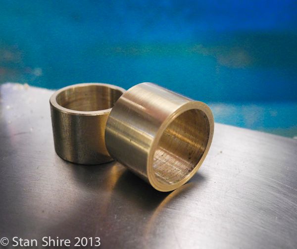
The two pieces are roughly to length. The action then moves to the mill to make both the same length and to mill a recess for the round bearing shells.
Ready for their debut on the soldering stage.
Thats todays output. More tomorrow. Dont change that channel.
Part 1
The way to succeed is to double your error rate.
Thomas J. Watson
Chairman and CEO of IBM
I had the plans for the RV-1 on the bench for a few months while I was working on the boiler. I was following Bill Lindseys build and didnt realize, until he finished it, that it was smaller than I had imagined. So, all dimensions times two seemed doable.
I printed a second set of the drawings and, with a calculator to check my math, wrote the new 2X dimensions on the plans.
I went through the brass and aluminum stores and ordered what I didnt have.
Most pieces laid out on the bench all ready for their weight reduction.

The base plate, a .375 6061 piece, becoming square.

The 2 face mill gives a beautiful surface.

Even with the DRO, I feel better marking out the piece. That way, I have a better chance of catching a screwup before it happens.

After finding the 0,0 corner and zeroing out the DRO, I plunged an end mill and began making the cutout for the flywheel. I changed to a smaller diameter end mill for the corners and finishing pass.

With the flywheel opening cut and mounting holes drilled, it was good to see that each hole was perfectly positioned on the scribe lines.

I like to mill a bevel on plates. Cutting the edge against the fixed vise jaw makes everything work nicely with the bevels all around matching at the corners. Cut, turn 90 degrees, cut, turn, etc.

First part done. Of course, more sanding and polishing will come later.

The flywheel bearing towers are next. I had seen these acetal bearings with stainless steel balls and though that this might be a good engine for a tryout. They are described as no lube if run under 2500 rpm. Maybe.

The primary problem is that they are wider than the .5 x .5 brass square. Even though there appears to be plenty of room for a wider piece, I had another idea. And Im not in love with straight square pieces.

That looks like it might fit.

A bit of drilling and boring got me just under what I need. The engineering data for the acetal bearings gives from 0 to -.003 interference. The bearing O.D. is .625.


Im going to line bore the last 1 or 2 thou when the blocks are mounted on the baseplate. For now, the bearing almost presses in.

Good enough for now so I parted off two pieces.

I wasnt overly concerned with the internal finish as that will go away when they are bored to size.

For the bottom of the bearing tower, I rounded off the corners of the .5 square bar.

The two pieces are roughly to length. The action then moves to the mill to make both the same length and to mill a recess for the round bearing shells.

Ready for their debut on the soldering stage.

Thats todays output. More tomorrow. Dont change that channel.
")


