Learning to use CAD

Home Model Engine Machinist Forum

Help Support Home Model Engine Machinist Forum:

This site may earn a commission from merchant affiliate links, including eBay, Amazon, and others.
See, it isn't just the help with engineering, your great! Many thanks....I will try your suggestion David. Mike
 
Well I downloaded the Microsoft Java machine and it loaded ok ........but........still crashes the same....... ???

Come up with an error code of 1722

I won't take up any more of this thread so it there is a quick fix/suggestion I will give it one more go before finding some big sheets of paper and a sharp pencil!
 
Your right when you say that most of us won't use the FEA and other advanced functions in the 3D cad packages, on the other hand if you are making a complex part or assembly of parts and need to make sure that everything is right and parts don't conflict or interfere with each other before cutting metal 3D is pretty much the only game in town. 2D is good for simpler things as is a drawing on the back of an envelope, it is all a matter of perspective.
 
I remember working on lots of drawings of machine layouts drawn on J3 sheets.

It can all be done with pencil and paper. But it can be done faster with 3D
However, I offer the following into evidence.

I had the pleasure of attending a club meeting one night and the guest speaker was none other than Rudy Kouhoupt.

He was giving a talk on mechanical design. Rudy is renown for flawless documentation packages. If you build it to his prints it works and that's all there is to it. He is also known for his hand inked drawings with full perspective assemblies. I have never finished a print that way, but I have tried to ink before That is a lot of tedious particular work!
Being the "sophisticated professional" ( laugh giggle) I asked a rather sophmorish question " Rudy, why have'nt you changed over to CAD?" fully expecting the "I hate computers...or such and such type answer.
He looked at me with just a touch of a scowl and his answer was most enlightening and unexpected and brought the room to dead silence.

"You can make changes too fast and as a result you don't think through the design up front"

He then showed the "layout" for a new engine design. It was nothing but center and phantom lines with some notes. But every line meant something. A very fast way to flesh out an idea if you experienced ( which he was) in doing it that way.

At first I was suprised by the comment, but he's right. A CAD package can not replace the brain driving it. A bad design is just that regardless of how it's drawn.
How ever you document your design, make sure you think it through! ;D

Dave
 
I would think that most people would sketch an idea out on paper before moving to the computer.

It is much easier to think with a pencil than a mouse but the mouse can draw more accurately than a pencil and doesn't need sharpening.
 
Hi Loose Nut,

That is exactly what I do. I guess I think in pencil. ;D
 
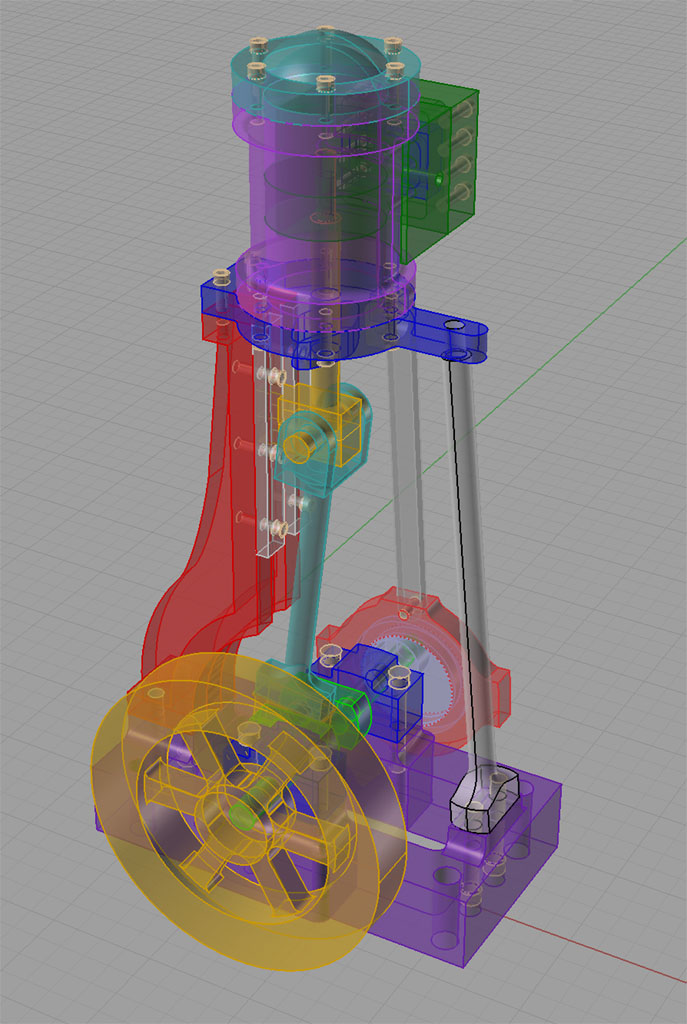
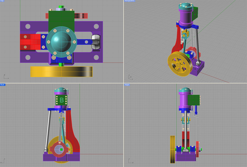
I spent a lot of time fussing over my choice of CAD program and ultimately settled on Rhino3D after trying several including Alibre. One of my biggest reasons for doing so is that it "thinks" the same way I do, so I can skip the pencil and paper sketch. I find it's easy for me to compose directly in Rhino and it goes very fast. Here's the most recent project I've done in Rhino:

PerspSep10.jpg


4ShotsSep10.jpg


Cheers,

BW
 
steamer said:
I guess I think in pencil. ;D

:bow: Old Draughtsmen never die ........... they may need sending for re-sharpening occasionally ........ but wth 8)

CC
 
I have used Turbocad for quite a few years and find it is great. I have Pro15 now and draw everything in 3D. It is great to be able to fit things together and see how they interact before cutting anything. I just purchased TurboCADCAM, so I am looking forward to trying that out. Here are some jpg's of some of my drawing (taken from magazines)


engine.jpg


Jemma 7 Cylinder Radial isometric withou case.jpg


Snow, Double Acting Engine iso with flywheel2.JPG
 
I find these 3D drawings close to works of art and many would justify framing an put on the wall. Excellent stuff. How many hours work to produce any one of the drawings?
 
Metal Mickey--If you think those are works of art, you'd love the walls of my office. thats all I do 8 hours a day, 5 days a week!!!---Brian

office walls001.JPG
 
Yes Brian but you get paid to do just that.
I get paid to make parts and if I spent hours drawing rendered images in 3D who pays ?

You only need to be able to draw enough to get the job done, in Brian's case it all the way as that's what his customer wants and is willing to pay.

You have to base how much time is spent drawing to how much is lost actually making the part.

TPUN%2016.jpg


This is a drawing of the business end of a boring bar. The green line is the trimmed shape, the red line is the pocket for the tip, small cross is 0,0 large cross is the centre for the holding screw.

That's all the CNC needs to be able to make one, no outer shape, no rendered drawings just what you see.
Anything else is wasted as that time could be better spent actually making the part.

That tool will bore a hole, the drawing will become blunt if you try to use that.

.
 
Part of my last job I restored an old steam tug to a working passenger vessel taking tourists for rides in the river and up and down the coast.

Some of the old blueprints were almost unreadable and some dimensions did not match those found on the actual machinery.

The answer was CAD so I bought Quickcad which was a 2D program produced by Autodesk. I could not get the hang of it! It was this layers business that had me boxed. One day the penny dropped and away I went.

My wife and I are building our retirement home to our own design. Quickcad was not up to the task so I went and bought Turbocad which seemed to offer the best value for money in my opinion. I have tried Autocad but it and I are not good mates so although it is the industry standard package I had to go elsewhere to save both my sanity and my hip pocket nerve from irreversible damage.

After our house plans and elevations were complete and in the hands of the builder, I though it would be nice if I produced a 3D drawing with different camera angles and walk throughs etc.

Suffice to say that so far the only thing of note is my complete lack of success. I am sure that as with my initial foray into 2D, my brain is not grasping some small but vital concept.

If anyone can give me and my penny a push so it will drop I would be a very happy man. ???
 
Working in 3D CAD is a bit like eating an elephant. It looks very impressive, but its done one bite at a time. I make some incredible assemblies, and animations. People say "Whooeee---Ya must be an Einstein!!"---'Taint so!! Even the most complex assemblies are made one part at a time, and to make one part, you draw it in 2D, just like the most simple and straightforeward Autocad. ---and then you extrude it to get that third "dimension". To put it in very simple terms, if you want a 3D model of a 2 x 4" x 24" long, then you draw a rectangle and dimension the sides to be 2" and 4", and the angles all to be 90 degrees. Then you hit the "extrude" button and type in a value (in this case 24" )and hit the "go" button. Bingo---You've created a 3D solid model. You drag all the individual "parts" (which each are created as a seperate "file" in your computer) into an "assembly" and use the "mate function" to assemble all the parts. The very first part that you put into an assembly file is automatically "fixed" in place. All parts added after the very first one are "floating"--meaning that the software can move them to wherever the "mate function" decrees that they have to go. The mate function is really neat--you assemble the individual "parts" just the same as you would if you were out in the garage putting real parts together. Say for instance that you have 2 "parts" that you want to put together--both parts have a hole in them. You use the "concentric mate" and highlite the hole in each part.--The software will move the "floating" part around automatically untill the holes are concentric. Then you determine which "faces" of the 2 parts you want touching each other, and after highlighting them, you use a "coincident mate"--The software will move the "floating" part untill the faces touch each other. Then you only have one choice left to make---What is the angular relationship you want between the 2 parts. (remember, the faces are touching each other, but the "floating" part can still rotate about the centerline of the 2 holes which are concentric). So you use an "angle mate" to click on the two parts and type in a value representing the angle you want between the parts--and the software will automatically move the parts into that relationship. Now both parts are "fixed". then you just keep adding "parts" and using the "mate" functions untill you have created an entire machine. The really great thing is that the individual "parts" or even major "assemblies" will create 2D drawings automatically---because you have already input all the math data when you were creating the "parts" in the first place. As a consequence, you don't really "draw" when you work in Solidworks 3D. You create "parts" and "assemblies" and any 2D shop drawing is 95% automatically created by the software. The remaining 5% being tolerances and notes that you type in manually.

2 x 4 Solidworks Demo.JPG
 
I did have a hard time grasping the concept of drawing in 3D for quite a while. My first drawings are all 2D and they work quite fine for what I need them for. I bought the TurboCad training books which were a great help, but then I found this website http://www.textualcreations.ca/index.html He has a whole bunch of tutorial that has help a lot to produce those images. You do have to pay for most of them, but worth it.
I spend a lot of time in remote camps waiting for pilots to bring back broken helicopters for me to fix, so I have a lot of time to work on these. Lot better than staring at a tent roof, cant go have a drink either as the camps are dry.
Don't forget, in CAD you only draw things once. The Snow double acting engine, there are 4 cylinder heads, only one has to be drawn. You them duplicate it and place it where you want it. Once one complete cylinder is done, you then copy it and now you have 2.
I have not worked with Solidworks but would like to give it a try, your pics are really good Brian, you do excellent work, thanks for sharing them
 
Brian,

Thanks for your concise explanation of the 3D concept, I will give it a try over the weekend.

Most guys I know have a keen interest in mating so I will keep the concept to the forefront of my endeavours ::) :)
 
Back
Top