Lapping Brass

Home Model Engine Machinist Forum

Help Support Home Model Engine Machinist Forum:

This site may earn a commission from merchant affiliate links, including eBay, Amazon, and others.

cfellows

Well-Known Member
Project of the Month Winner
Joined
Aug 25, 2007
Messages
3,890
Reaction score
715
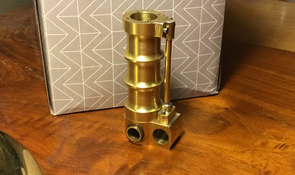
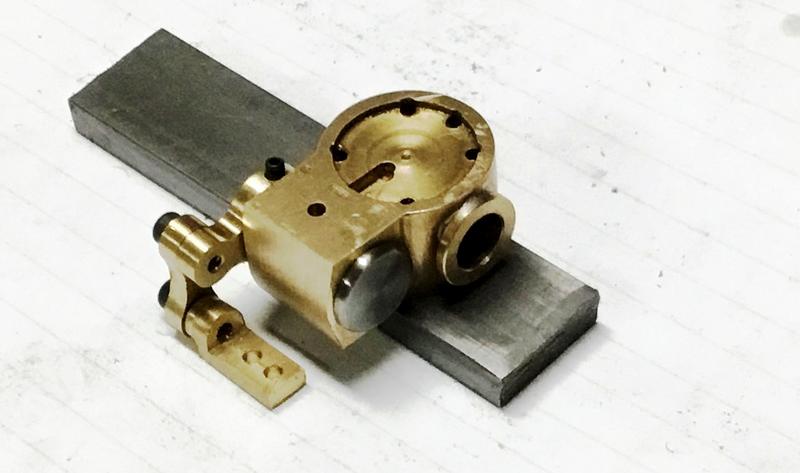
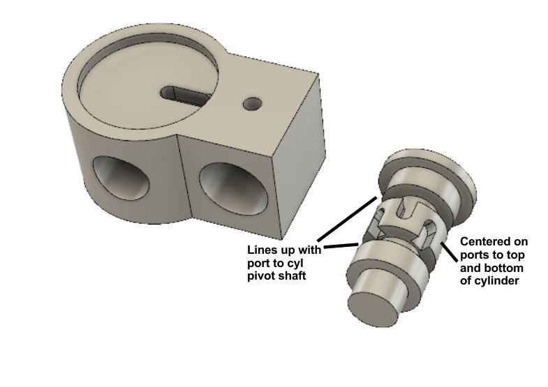
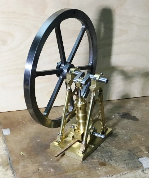
I'm building a small, double acting steam engine modeled after a design by Henry Maudslay. The engine uses a 3/8" diameter, 5/8" long stainless steel rotary valve which rotates inside a brass valve block.

To reduce air leakage, I am trying to lap the valve bore in the brass valve block and am making a new, stainless steel rotary valve which I also want to lap. Hopefully, by lapping both the valve bore and the valve I can reduce air leakage to a minimum.

I'm new to lapping and have been trying to use a barrel lap on the valve block bore. The barrel lap is also made of brass and I'm not convinced that lapping brass with brass is working all that well. Next I'm considering making a lap from lead (or melted solder) and trying that. I'm also considering a lap made from wood.

Finally, the lapping compound to use is also a mystery to me. I've read suggestions from Bon Ami to toothpase to Timesaver. The grits seem to start at around 600 and work up to 1200.

If anyone has some experience lapping a brass ID to a pretty high degree of roundness, straightness, and finish, I'd sure like hear from you .

Chu
 
I lapped the bore in the Edwards vacuum pump of bronze and i used the long wood pin who are turned to true in parallel with saw split to fasten the fine sandpaper and wrap around. Lap very short time and move in whole length to remove tool marks only. To make more precision in parallel as possible: Use reamer first and remove tool marks as i wrote above.

To keep in long life, it must be cross hatched in surface too keep oil inside the "valleys" and lubricate the moving parts.

See the movie of the Edwards vacuum pump under test. The piston is without piston ring or gasked.
 
The lapping principle uses a lap that is softer than the workpiece so that the abrasive will tend to embed in the soft lap rather than in the workpiece. The lap has to have good dimensional stability if uniform cutting is expected. Rather than lead or solder, you might try using annealed copper (which should be softer than most brass stock) with diamond abrasive. Diamond grit in many different sizes is available in small quantities and has an affinity for copper for some reason. Diamond cuts fast and lasts a long time. Finishing up with 1200 or 1500 grit would probably be good enough.

I think you are likely to find that lapping brass with precision is going to be tedious and haphazard at best. Also, its wear resistance against stainless steel would not be the best. I suggest making a liner of steel for the brass valve body and making the rotary valve of phosphor bronze or cast iron. Those materials would last a long time and be much easier to finish to the required precision.

WOB
 
Hi Chu,

I don't hold out much hope of you lapping the brass ! Yes you will certainly be able to polish it, quite possibly to a mirror finish, but I don't think you are going to achieve your objective.

Good Luck anyway, I will watch your progress with interest.
 
Mirror polishing the surface is not good idea due lack to keep oil in the "valleys" in the surface.
 
I have to disagree with WOB, Baron and Jens. Lapping brass is perfectly feasible and is the best way to get the finest fit. It is time consuming and requirese the development of a bit of skill in getting the feel. For brass, a lead lap should be good, but annealed copper is fine too as is aliminium, which I have used successfully in lapping pump bores for full sized steam locomotive lubricator pumps.

As to lapping medium, I would not consider using diamond. It "cuts fast and lasts a long time". You do not want either of these qualities. Silicon carbide is too harsh for brass parts this small. Brownells will sell you 600 grit garnet. I have some, but I think even that is too harsh for light lapping in brass. I have never used Timesaver as it is expensive in the UK, but if you have some in a fine grade, it may well be what you want as it breaks down and loses its cutting ability quite quickly. That is what you want. What I have used successfully on brass is Brasso liquid metal polish. It is surprising how quickly this will cut.

The lap needs to be capable of expanding, to be barrel shaped, that is to say fat in the middle by several thou, and to be reasonably round to start with. You start with it an easy fit in the hole to be lapped so that you can easily hold the part in your fingers (be ready to let go if it grabs!) as you move it steadily back and forth over the charged lap running at a comfortable speed, say 200 rpm for a 3/8" hole. As you expand the lap little by little you will feel where the bore is tight and needs more concentrated work. Wash it out very thoroughly and measure it regularly.

For the stainless valve you can use a little rectangular lump of copper, slit, with a pinch bolt. Fine silicon carbide with light oil should be OK for this. In this case you hold the lap and spin the work.

For your valve you do not want to leave a cross hatch pattern. That is for honed IC engine cylinder bores, not brass rotary valves. You should ideally end up with a polish. Stainless and brass will make a good combination for your valve, if both are well polished and a fine fit.

I have described the process of lapping gunmetal bearing bushes here http://www.charleslamont.me.uk/Seagull/bearings.html starting at 2010-09-22.
 
Hello Charles,

Thank you for your informative notes. I've never had much luck with brasses, I always seem to end up with a high polish that seems to grab and scratch easily.
 
John and all

I'm going back to , well beyond the days of Yore when I got for a Christmas a cheap copy of a Mamod dribbler.

I can't imagine that in mass production, cheap as chips, that anyone would have time to do anything more than boring.

Fast forward a bit to the time that I could barely afford on National Service and 4 bob a day- for everything that came my way-- but I could just manage Sparey's, the Amateur's lathe. It gave and still gave detailed know how on how to bore things like his 5cc diesel. All sorts of abrasives such as 'brick dust'-- go figure as our cousins say.
Fast forward a little more to much lamented but pedantic George Thomas who wrote about from a lathe which had it tailstock, off cock but it bored perfectly parallel- but obviously oversize but - as I repeat DEAD parallel. In another chapter Thomas deals with the blunt fact that his homemade boring tools were better than his bought out reamers.
At much the same time, Prof Chaddock comes along with perhaps the first decent tool and cutter grinder available to we amateurs. It needed the ability to bore THREE holes at an 1" diameter so that the whole panjandrum would traverse the on exactly 3.5" apart-- WITHOUT binding! His mate, Thomas again came up wiith a very simple but precise boring bar but yet again, it was empirically and mechanically sound because it was 'IN LINE'

The only possible bug bear was that the lathe bed might be worn or warped.
As John knows, I have- roll of drums- a Quorn and a less noisy fanfare, an inline boring bar-- somewhere now.

Today, the real World, I have an odd task in boring a 43mm collar thing to rotate at 90 degrees ie both ways on a Sieg boring table as I want to drill in the 3rd dimension- but that's me.
So there you have it. Sparey, Thomas and Chaddock.

A little idle thought is that - well, I can prepare a lathe tool which will mirror finish steel - so when I bore internally, I should get similar results.

Which , gentlemen, is where the difficulty erupted.

Cheers

N
 
Thanks, everyone, for the informative responses. First, a picture of the cylinder with the valve block at the bottom...

SNSpXjL.jpg


And a picture of the valve block with the valve and linkage assembly in place...

9cOfxXI.jpg


Drawing of the valve block and (old valve)...

aAlQNqt.jpg


And a picture of the engine nearly completed...

ZByvlrq.jpg


At the moment I am undecided which path to take on this valve assembly. After reading all the posts and what I could find on the internet, I had decided that a steel sleeve might be a better alternative. Information on lapping brass is scarce, both in terms of lapping tool material and recommended lapping compounds. Garnet and Timesaver seem to be the only two products to which I could find reference. The problem is exacerbated by 4 radial holes or ports which have already been drilled into the valve block bore. I'm not sure how these holes affect the lapping process but they do affect the measuring process. The tool I have been using to measure my progress is a Starrett bore gauge from this set..

kmTSURo.jpg


I've measured the uniformity of the bore by setting the gauge to a close sliding fit then moved it back and forth in the bore to look for high or low spots. Unfortunately the ports seem to affect the "feel" of the gauge as it slides back and forth. So, I'm not really certain if my bore is uniform.

Last night I decided that a steel sleeve, Loctited into the brass bore after enlarging it might be a better alternative. I made the sleeve with an OD of .4375" and ID of just under .375". I first removed most of the internal tool marks with a number of wraps of wet or dry silicon carbide sandpaper wrapped around a split aluminum rod, first 400 grit then 600 grid. I followed this up using diamond lapping compound and brass barrel lap, first 20 micron then 14 micron. The finish looks almost mirror like at this point and the bore gauge slides from one end to the other with no discernible change in the resistance.

The problem will be, of course that once I drill the 4 ports through the steel bush, the bore will need dressing to remove the burrs and I don't know how difficult that will be. After reading Charles's post, I'm tempted to continue with just the brass bore, perhaps locating some Brasso and see how that works. I could make a lap out of aluminum and could also manage something out of lead (or perhaps solder). I've even seen suggestions of a hardwood dowel with a slit as a lapping tool. In any case, measuring and assessing my progress and results remain the largest problem.

Boy, and I thought lapping was supposed to be easy...

Chuck
 
Chuck,
I've lapped aluminum with Timesaver and an wood (oak) dowel that I turned into a barrel over a short portion of its length. If you have to remove a lot of material to correct a major taper or out-of-round condition, it may not work, but on the other hand you have the sleeve to fall back to.
Terry
 
Chuck,

That is turning out to be a beautiful engine. I've been following, but I guess I couldn't visualize how nice it would look with the parts put together.

You've got some nice bling just in a pleasing design and execution.

Thank You for posting.

--ShopShoe
 
Hi Chuck,

Chrome metal polish works and is possibly bit sharper than Brasso. Also Jif/Ajax cleaning liquids, the ones that are white and feel coarse to the fingers, are more aggressive still. Maybe not all are available in your neck of the woods.
 
I wanted to follow up and let folks know how this turned out. First, let me say, at the end of the day, I wasn't feeling very confident about my results. I simply had no good way to measure my results. But, when I assembled the engine and hooked up the air, I was delighted with the results. There is little or now discernible leakage and the engine runs forward and reverse from very slow to very fast.

Here is a picture of the lapping tools I made and used. A bit crude, perhaps, but boy did they work!

01M8PCE.jpg


The top image is the OD lap. It's a 13/16" brass disk, 3/8" thick with a .385" hole in the center. I made the slits with my 4x6 bandsaw. I used a die holder to hold it and squeeze it together to adjust the diameter. To lap the stainless steel valve, I started with fine, clover silicon carbide lapping compound, then moved on to 20 micron diamond paste for the finish. Using a micrometer, the diameter seemed to be uniform and circular.

The ID lap was made from a piece of 3/8" diameter aluminum rod. I used a .032" slitting saw to make the axial slits in from both sides. The slits connect for about 75% of the length. I center drilled a #29 hole from the end thru to the center of the slit. Then I tapped it for an 8 -32 SHCS. The short piece of sharpened rod is 1/8" drill rod. By inserting the drill rod and the screw, the point pushes the slits apart when it reaches the end of the center drilled hole. I found this to be very nice lap, able to adjust the diameter in pretty fine increments. I had tried many different lapping compounds on this piece, but in the end, finished it up with some Timesaver yellow lapping compound that Terry Mayhugh had given me. I mistakenly mixed the powder with water instead of oil, but it seemed to work fine and gave me a nice, uniform finish.

I was concerned about the fit because when I was all done, the valve slipped into the valve block with little or no resistance. But I must have gotten a good fit because it isn't leaking any air that I can tell.

Chuck
 
Chuck. That is one really nice engine you have there!!

I'm glad you got plenty of responses because I had not idea as to your lapping question. I believe I learn something new every time I log into this forum.
 
Back
Top