I am working on an experimental project and I have now reached the stage where I can do some research on lamina engines.
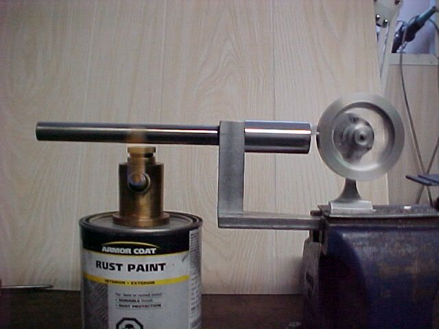
The tube is 6" long .625" OD and made out of mystery metal. It was in my scrap brass box as I thought it was plated brass plumbing pipe but appears to be a magnetic stainless. I silvered soldered a plug in the end and threaded the other end 32 TPI. I stuffed a bunch of steel wool into the bottom of the tube.
The support post is 7075 Aluminum. A scrap piece just cleaned up, bored .625" 32 TPI threaded all the way through. With the tube screwed in, there is an O ring to make the seal to the cylinder.
The cylinder is 1.125" 6061 aluminum 2" long bored out for a .750" piston and one end stepped down to .625" and threaded 32 TPI. The inside of the step is bored and threaded 3/8" x 16 TPI. I made a plug 3/8" x 16 with a 1/4" hole and an insert with a 3/16" hole. This gave me three choices of restrictor size to try and get the engine running.
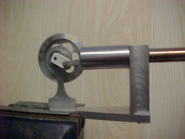
The crank assembly is straight forward. Ball bearings with the grease washed out and a 2 1/4" OD aluminum flywheel with six 1/4" brass inserts in the rim to add weight. The flywheel rim is 1/2" wide and the inserts go all the way through. There are two short copper inserts to balance the weight of the crank arm which has a basic connecting rod onto a graphite piston.
I probably spent four hours before I had it running and was intrigued by the fact that when spinning the flywheel, it would always stop with the piston in the middle of its stroke, never at either end. I had expected that heating the tube would cause the air to expand and push the piston out and just sit there, if running conditions were not being met.
The trial run shown in the picture was about 5 minutes with the 1/4" restrictor. Now the fun starts to experiment with different restrictor size, different tube length, different amount of steel wool, etc. On the trial run, I did find that changing the position of the flame along the tube had little effect on speed. Obviously, it will be a long time before final pieces are made and a displayable model assembled.
The tube is 6" long .625" OD and made out of mystery metal. It was in my scrap brass box as I thought it was plated brass plumbing pipe but appears to be a magnetic stainless. I silvered soldered a plug in the end and threaded the other end 32 TPI. I stuffed a bunch of steel wool into the bottom of the tube.
The support post is 7075 Aluminum. A scrap piece just cleaned up, bored .625" 32 TPI threaded all the way through. With the tube screwed in, there is an O ring to make the seal to the cylinder.
The cylinder is 1.125" 6061 aluminum 2" long bored out for a .750" piston and one end stepped down to .625" and threaded 32 TPI. The inside of the step is bored and threaded 3/8" x 16 TPI. I made a plug 3/8" x 16 with a 1/4" hole and an insert with a 3/16" hole. This gave me three choices of restrictor size to try and get the engine running.
The crank assembly is straight forward. Ball bearings with the grease washed out and a 2 1/4" OD aluminum flywheel with six 1/4" brass inserts in the rim to add weight. The flywheel rim is 1/2" wide and the inserts go all the way through. There are two short copper inserts to balance the weight of the crank arm which has a basic connecting rod onto a graphite piston.
I probably spent four hours before I had it running and was intrigued by the fact that when spinning the flywheel, it would always stop with the piston in the middle of its stroke, never at either end. I had expected that heating the tube would cause the air to expand and push the piston out and just sit there, if running conditions were not being met.
The trial run shown in the picture was about 5 minutes with the 1/4" restrictor. Now the fun starts to experiment with different restrictor size, different tube length, different amount of steel wool, etc. On the trial run, I did find that changing the position of the flame along the tube had little effect on speed. Obviously, it will be a long time before final pieces are made and a displayable model assembled.