


In September 2008 I started playing with lamina engines and posted a thread at
http://www.homemodelenginemachinist.com/index.php?topic=2841.0
In January and February of 2009 I did some more work and then in December of 2009 I got Jan Ridders plan for the Pulse Mobile. I finished up all the machine work (except for fitting the heat tube) when I found out that the tube called for in the plan is not sold in North America. The plan calls for a tube 18mm x 180mm while the North American standard is 18mm x 150mm. I found one locally that was obviously an import from a low wage country because the quality made it totally unusable. It was not round and after cutting off the malformed rim I found that the inside of the tube had .004" taper in the two inches required for the cylinder.
Putting the Pulse Mobile at the back of the bench, I retrieved my test setup from 2008 and started again. After 18 months, I still don't know WHY a lamina engine works but I do know WHAT makes them work.
If we look at the basic lamina engine, we see that it has three assemblies. The heat tube, the cylinder assembly and the flywheel assembly.
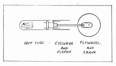
The Heat Tube
Starting with the heat tube, I found that the most important thing is the thermal conductivity of the material. Pyrex (borosilicate glass) appears at the extreme end of thermal conductivity charts of all the materials that might be of practical use in building a lamina engine in the home shop. The nearest handy thing is stainless steel and it is more than a factor of ten removed from Pyrex. In my earlier experiments, I had limited success with stainless steel and zero success with mild steel, brass or aluminum. A Pyrex test tube can be held in the bare fingers at one end while the other end is heated to several hundred degrees. This feature shows up in the lamina engine where virtually no heat is transferred to the cylinder.
One end of the heat tube is stuffed with steel wool or stainless steel pot scrubber material which is generally referred to as the regenerator. Whatever it's title, it acts to transfer heat to or from the empty portion when pressure in the tube changes.
The Cylinder Assembly
The cylinder can be made out of any material and in some designs the heat tube itself is used for the cylinder. The all important part is the fit of the piston in the cylinder. It must be an easy sliding fit but close enough that you can't push or pull the piston while blocking the hole in the cylinder head. I made pistons out of graphite as it is easy to fit with 1200 grit paper and doesn't require any lubrication. The piston uses a conventional cross head and connecting rod and must be very close to the cylinder head at top center. In these tests, the con rods had no bearings or lubrication, just aluminum rod on steel pins.
The heat tubes I use are 18mm which have a nominal .625" ID so I made the cylinder a nominal .750" ID on my theory that would give increased compression. This may be an incorrect theory, but it worked for me.
When the heat tube is affixed to the cylinder, any movement of the flywheel should result in a springback. When using a metal cylinder, sealing of the heat tube to the cylinder is tricky. O rings are the accepted method but the slightest bit too tight and the glass tube will break. My tests were done without a retaining ring to facilitate quick changes of components and it was necessary to have the end of the tube against the vice while running or the tube would blow off.
The Flywheel Assembly
This is a conventional assembly with ball bearings and I have no suggestions as to diameter or weight required. My crank is a disc with crankpin holes tapped at radii of .250", .375" and ..500" to make changing piston stroke easy.
Operation
The engine is run by putting a small flame under the heat tube close to the interface of the regenerator and empty space. I found no change in speed when the flame was positioned about half the width of the flame under the regenerator to a distance of about .5" away from the regenerator.
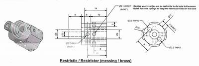
We now come to the most discussed point on lamina engines - the Restrictor. From nothing to the elaborate design of Jan Ridders shown in the drawing below, there is an endless amount of published theory. I see no engineering logic to the Ridder design, but it is a great exercise in machining. Too bad that it is hidden from view in the final assembly.
I worked with simple round restrictors of five different diameters and two different lengths. The chart below shows the different speeds obtained with nothing changed except the restrictor. Without any method of measuring the torque, I don't don't know if total power output changed, or if torque went up as speed went down. .The following speed checks were run: The second column shows the same speed checks run several days later. Nothing very definitive, but it definitely runs faster with the ..250" restrictor and indicates that a shorter restrictor might be beneficial.
Restrictor length by diameter and speed obtained on a 1" stroke.
.660" x .125" 0 RPM 0 RPM
.660" x .187" 205 RPM 0 RPM
.660" x .250" 230 RPM 280 RPM
.660" x .315" 239 RPM 218 RPM
.660" x .375" 183 RPM 140 RPM
.200" x .315" 290 RPM 235 RPM
.200" x .250" 325 RPM 308 RPM
I tried to run this setup on both .500" stroke and .750" stroke. It would not run on the .500" stroke and obviously did not have enough compression. On the .750" stroke it ran at 154 RPM with the .200" x .250" restrictor and at 114 RPM with the .200" x .315" restrictor.
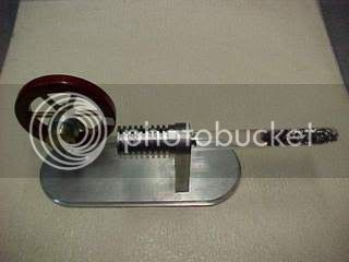
This picture shows the engine setup that I ran these tests on
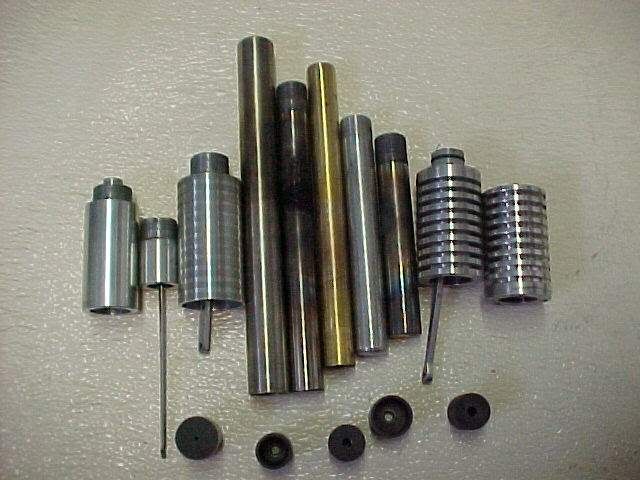
This picture shows some of the parts that had been pushed to the back of the bench over the last eighteen months of this project.
That does it for me. I will now complete my Jan Ridder Pulse Mobile with a 18mm x 150mm test tube and a metal cylinder and probably never look at another lamina engine.
http://www.homemodelenginemachinist.com/index.php?topic=2841.0
In January and February of 2009 I did some more work and then in December of 2009 I got Jan Ridders plan for the Pulse Mobile. I finished up all the machine work (except for fitting the heat tube) when I found out that the tube called for in the plan is not sold in North America. The plan calls for a tube 18mm x 180mm while the North American standard is 18mm x 150mm. I found one locally that was obviously an import from a low wage country because the quality made it totally unusable. It was not round and after cutting off the malformed rim I found that the inside of the tube had .004" taper in the two inches required for the cylinder.
Putting the Pulse Mobile at the back of the bench, I retrieved my test setup from 2008 and started again. After 18 months, I still don't know WHY a lamina engine works but I do know WHAT makes them work.
If we look at the basic lamina engine, we see that it has three assemblies. The heat tube, the cylinder assembly and the flywheel assembly.
The Heat Tube
Starting with the heat tube, I found that the most important thing is the thermal conductivity of the material. Pyrex (borosilicate glass) appears at the extreme end of thermal conductivity charts of all the materials that might be of practical use in building a lamina engine in the home shop. The nearest handy thing is stainless steel and it is more than a factor of ten removed from Pyrex. In my earlier experiments, I had limited success with stainless steel and zero success with mild steel, brass or aluminum. A Pyrex test tube can be held in the bare fingers at one end while the other end is heated to several hundred degrees. This feature shows up in the lamina engine where virtually no heat is transferred to the cylinder.
One end of the heat tube is stuffed with steel wool or stainless steel pot scrubber material which is generally referred to as the regenerator. Whatever it's title, it acts to transfer heat to or from the empty portion when pressure in the tube changes.
The Cylinder Assembly
The cylinder can be made out of any material and in some designs the heat tube itself is used for the cylinder. The all important part is the fit of the piston in the cylinder. It must be an easy sliding fit but close enough that you can't push or pull the piston while blocking the hole in the cylinder head. I made pistons out of graphite as it is easy to fit with 1200 grit paper and doesn't require any lubrication. The piston uses a conventional cross head and connecting rod and must be very close to the cylinder head at top center. In these tests, the con rods had no bearings or lubrication, just aluminum rod on steel pins.
The heat tubes I use are 18mm which have a nominal .625" ID so I made the cylinder a nominal .750" ID on my theory that would give increased compression. This may be an incorrect theory, but it worked for me.
When the heat tube is affixed to the cylinder, any movement of the flywheel should result in a springback. When using a metal cylinder, sealing of the heat tube to the cylinder is tricky. O rings are the accepted method but the slightest bit too tight and the glass tube will break. My tests were done without a retaining ring to facilitate quick changes of components and it was necessary to have the end of the tube against the vice while running or the tube would blow off.
The Flywheel Assembly
This is a conventional assembly with ball bearings and I have no suggestions as to diameter or weight required. My crank is a disc with crankpin holes tapped at radii of .250", .375" and ..500" to make changing piston stroke easy.
Operation
The engine is run by putting a small flame under the heat tube close to the interface of the regenerator and empty space. I found no change in speed when the flame was positioned about half the width of the flame under the regenerator to a distance of about .5" away from the regenerator.
We now come to the most discussed point on lamina engines - the Restrictor. From nothing to the elaborate design of Jan Ridders shown in the drawing below, there is an endless amount of published theory. I see no engineering logic to the Ridder design, but it is a great exercise in machining. Too bad that it is hidden from view in the final assembly.
I worked with simple round restrictors of five different diameters and two different lengths. The chart below shows the different speeds obtained with nothing changed except the restrictor. Without any method of measuring the torque, I don't don't know if total power output changed, or if torque went up as speed went down. .The following speed checks were run: The second column shows the same speed checks run several days later. Nothing very definitive, but it definitely runs faster with the ..250" restrictor and indicates that a shorter restrictor might be beneficial.
Restrictor length by diameter and speed obtained on a 1" stroke.
.660" x .125" 0 RPM 0 RPM
.660" x .187" 205 RPM 0 RPM
.660" x .250" 230 RPM 280 RPM
.660" x .315" 239 RPM 218 RPM
.660" x .375" 183 RPM 140 RPM
.200" x .315" 290 RPM 235 RPM
.200" x .250" 325 RPM 308 RPM
I tried to run this setup on both .500" stroke and .750" stroke. It would not run on the .500" stroke and obviously did not have enough compression. On the .750" stroke it ran at 154 RPM with the .200" x .250" restrictor and at 114 RPM with the .200" x .315" restrictor.
This picture shows the engine setup that I ran these tests on
This picture shows some of the parts that had been pushed to the back of the bench over the last eighteen months of this project.
That does it for me. I will now complete my Jan Ridder Pulse Mobile with a 18mm x 150mm test tube and a metal cylinder and probably never look at another lamina engine.