Kyle's Edwards Radial build.

Home Model Engine Machinist Forum

Help Support Home Model Engine Machinist Forum:

This site may earn a commission from merchant affiliate links, including eBay, Amazon, and others.
Hi Kyle,

I gave the link to the vices in my last post above.

Where you might be going wrong with your sitting down of the part is that maybe you are hitting it too hard and it is bouncing up off the vice base.

I always use a dead blow lead hammer that I make myself, but I don't hold it by it's handle but by the small head. That way you won't hit too hard, and it really is only a small tap. Gently tap down in different places on the part until both ends of the parallel are down solid. A large cylindrical fishing weight should be good enough to use as my small lead hammer heads only weigh about 8oz.

The small ones are the ones I use mainly, and once they are too flat to be used, I melt the lead off the stainless tube handles and recast new heads. This lot should last a few years.

Yammers.jpg


John
 
John,
Sorry not sure how I missed that obvious link.

That vice looks great. I'd ask how much but well I'm planning for a wedding lol I think I'd rather not know.

Can you use a soldering gun to break the loctite free? I used to do that when working on rc helicopters.

As far as the lead hammers, I have a bunch of wheel weights and bullets which I don't reload that caliber. However, I'd need to coat the raw lead with something to seal it.

I got the rocker buttons wrapped to their final shape and dimensions.

View attachment ImageUploadedByModel Engines1459041352.736210.jpg

View attachment ImageUploadedByModel Engines1459041367.872038.jpg

View attachment ImageUploadedByModel Engines1459041380.027823.jpg

All thats left is to harden and polish. I still am playing around with this oil hardening drill rod. I won't harden the buttons until I feel comfortable with the technique.

Thanks for looking
Kyle
 
I snuck away after Easter lunch and hammered out the oil pump plunger.

View attachment ImageUploadedByModel Engines1459123638.096508.jpg

View attachment ImageUploadedByModel Engines1459123651.502446.jpg

View attachment ImageUploadedByModel Engines1459123669.045938.jpg

I also got a nice Easter surprise. I never knew my grandfather on my fathers side, he died when I was three. When my dad found out I was working in this engine he said I have your grandfathers micrometer that I can have.

He found it, its a little rusty but seems in working condition. It even calibrated well and is pretty close to my 1" standard, which is a little rusty too.....

View attachment ImageUploadedByModel Engines1459123920.854255.jpg

View attachment ImageUploadedByModel Engines1459123937.579416.jpg

View attachment ImageUploadedByModel Engines1459123953.272406.jpg

The anvil is a little rough, I would love to be able to use them so I'm considering a trip to the Starrett repair place. Its about 1 1/2 hours from where I live. Can they fit a new anvil and rod part?

View attachment ImageUploadedByModel Engines1459124093.559669.jpg

Thanks as always for looking

Kyle
 
I've been making small amounts of progress though nothing is completed yet. An order from McMaster brought both a phospher bronze rod and a 1" diameter ductile cast iron rod for the rings.

Before I left work I hogged out the center and roughed out the center of the Iron.

View attachment ImageUploadedByModel Engines1459637046.512725.jpg

View attachment ImageUploadedByModel Engines1459637066.170838.jpg

The south bend at work is in a bit of disrepair and Im not familiar with it. I left a decent amount to clean up on my lathe. I just found out the other day a bushing in the gearbox is seized, so no threading for a while.

I started to remake the valve guides. This time I'm going to center drill on the lathe, then drill and ream on the mill before making the flats on the head.

I also got in a replacement 1/4" 7075 plate and a 7/8" plate of 4340 steel. The steel was $10 shipped from eBay.

I printed two crankshaft drawings and counterweights to plan out my cuts. I know what your thinking, why two? Well lets be honest there's a good chance I'll have to remake it.

View attachment ImageUploadedByModel Engines1459637337.075693.jpg

View attachment ImageUploadedByModel Engines1459637346.981200.jpg

View attachment ImageUploadedByModel Engines1459637364.957000.jpg

Im going with the last picture, I'll lob of the counterweights with the horizontal bandsaw then cut the rest with the do-all at work on Monday. The actual turning will have to wait until I get a 4 jaw chuck.

Thats all for now

Kyle
 
On a side note, I got a lathe threading bit yesterday. I wanted to learn threading, it seems less aggressive than the die on the valve guides. I pulled off the wax coating to find the tip was flat, about 1/32".

View attachment ImageUploadedByModel Engines1459642646.390572.jpg

Will this work for cutting a 1/4-28 thread? I always thought threading tools would have a sharp point, but Ive never seen one before.

Either way I'll have to wait until I get a 35 tooth gear so I can cut 28 tpi.

Thanks everyone
Kyle
 
I personally would be reluctant to use that tool, purely because of all the different types of thread used.

You would get away with it if the thread had a round bottomed profile but not if a sharper tip was reqired, the thread would bind or even lock up.

ALL the brazed on tipped thread cutting tools that I buy go to a full point, to get over the above problem.

If you can measure the exact width of the flat tip, with a few calculations using this chart, you should find out if the thread form you want can be safely cut with that tool.

Thread%20Forms_zpsn8yw9ovz.jpg


For a quick example, you WOULDN'T be able to cut either of the US Pipe Threads.

Hope this is of help

John
 
Last edited:
Hello everyone,

Although a did a short stint with model ship building, I've done some more work on the radial.

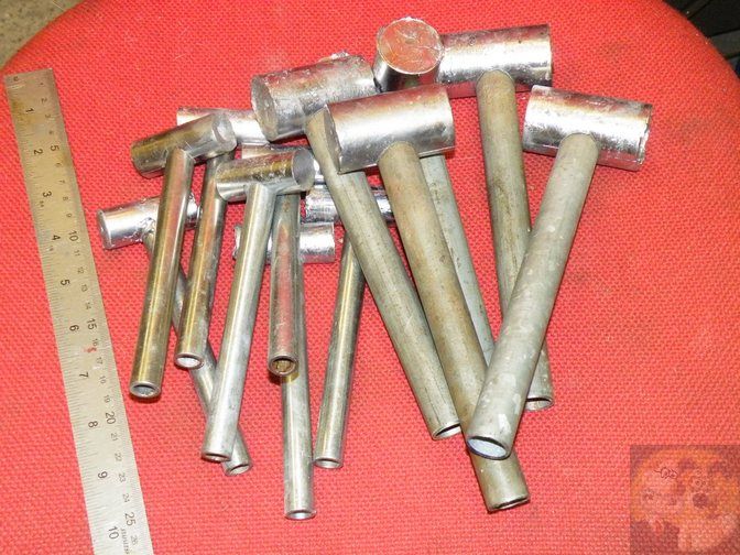
I was a bit frustrated with threading, I put it aside for a while. I finally committed and have twelve valve guides. I'm on the fence about using them right now but I'll consider it more when I get to the heads.

View attachment ImageUploadedByModel Engines1469149936.660717.jpg

I drilled and tapped a 1/4-28 hole into a block of aluminum, the guides were threaded in, located and drilled at .120" and reamed to .125". I still have to rechuck the valves and remove about .0015".

I started working on the crankshaft. It began with a 7/8" 4340 plate sawn to shape.

View attachment ImageUploadedByModel Engines1469150116.444968.jpg

View attachment ImageUploadedByModel Engines1469150146.525101.jpg

View attachment ImageUploadedByModel Engines1469150183.113081.jpg

View attachment ImageUploadedByModel Engines1469150200.555022.jpg

I left each section except the threaded section over by .002", .001" to sand out a slight taper that I couldn't seem to dial out, the other half for after heat treating. It still needs threading for the prop nut, gear pin and counterbalance mounting threads.

I ordered 12" by1.75" 7075 for the cylinder sleeves. I chopped it up with a portaband.

View attachment ImageUploadedByModel Engines1469150414.779433.jpg

View attachment ImageUploadedByModel Engines1469150438.141517.jpg

Lastly I've been doing some work on the rockers. This time I left excess that will be removed on the rotary table.

View attachment ImageUploadedByModel Engines1469150505.108696.jpg

View attachment ImageUploadedByModel Engines1469150557.710183.jpg

I've been using the wiggler to locate holes for drilling, line it up and dimple the metal. Compared it to my scribe marks and adjust. It's the best luck I've had drilling accurately located holes.

View attachment ImageUploadedByModel Engines1469150679.113189.jpg

View attachment ImageUploadedByModel Engines1469150696.287980.jpg

Next they'll go on a mandrel on the lathe to turn down the side bosses. These are rather complicated parts to me so it's taken a while for me to come up with the order of operations.

Lastly I got myself a new toy. I was stressing about the larger parts to make, having the crankcase and cam cover pieces cut to length I was thinking about getting a larger chuck, though that still doesn't help with future projects.

View attachment ImageUploadedByModel Engines1469151041.550109.jpg

I know it's not old iron, but I couldn't stand to have the lathe stick so far out with my limited space and I had gotten comfortable with the mini-lathe. It's a 10"x22" grizzly variable speed, $1300 from Craigslist, never used and still in the cosmoline. He had the qctp for it, tailstock chuck, a bunch of lathe bits and factory 3 and 4 jaw chuck and faceplate. I have to wait until I can finish off the basement to use it, but it'll be there waiting for me.

That's all for now
Kyle
 
A guy can never have too many lathes. Well done.
 
Thank you Hopper,

I'm hoping the heavier and stiffer machine will translate into nicer and more accurate parts.

Not much time this weekend, fiancé had wisdom teeth out and overtime at work.

I made a mandrel sized at .1252" from drill rod then heated and pressed a rocker arm on.

View attachment ImageUploadedByModel Engines1469415927.152139.jpg

Then I turned the width down to .200" and .170" where the boss is.

View attachment ImageUploadedByModel Engines1469416034.003803.jpg

View attachment ImageUploadedByModel Engines1469416001.106982.jpg

I'm not happy with this part, it was difficult to keep the rocker perfectly true and as a result the holes for the valve adjustment and hardpoints aren't centered. I will bet emailing this one.

The second attempt I only focused on turning the inner section.

View attachment ImageUploadedByModel Engines1469416124.497924.jpg

This is the final width and when I radius the ends I will tie back into this section.

That's all for now

Kyle
 
so far you look like you are doing good. Minor suggestion on your valves. Over the years I have found t6hat you want to change position of the valves as little as possible. I have used drill rod for mine and have never had as problem. In one setup you can do the OD, do the root radius The keeper groove and the valve seat taper and part them off all at the same setup in the lathe. Turn back the stem diameter to about .025 full back to about .025 past the valve end of the stem groove. use your groove tool now to cut the groove(remember to go to the full depth on the groove at this time. When turning the stem diameter you can use a tool with the root radius ground on it to do the turning at this point, leave about .0005 to polish off unless you can turn it to exact diameter w/a good finish. Now just come in with a tool with the valve seat angle ground into it and machine the face with just a plunge cut. Do it this way and the stem and angle will be concentric. part the valve off about .01-.015 full and later you will just have to face off the valve and not have to worry about concentricity. Before parting off break all edges with a ground tool used for making the valve seat angle (usually it is 45 deg.) So if you modify a threading tool to a 45 deg. left and right will work great.
I had a special tool made up for doing the valve seat. when doing the head you can rough the valve seat with a 90 deg. counter sink or I like to use 90 deg. spot drill. now the tool was a 4 fluted countersink that I had ground back leaving a 1/8 pilot and 45 deg. cutting edges. Even if the stem size on future projects may be bigger all you have to do is add some brass tubing(K&S from the hobby shop or make your own pilots and keep as a set.Well I have spouted along enough now just wanted to pass on what I found easiest.Keep up the good work
Tomb29
 
Back
Top