Kozo A3 in 1.5" scale

Home Model Engine Machinist Forum

Help Support Home Model Engine Machinist Forum:

This site may earn a commission from merchant affiliate links, including eBay, Amazon, and others.
Today's project was to finish the lubricator linkage. The photo is pretty self-explanatory:

Did you add that view port to the lubricator? Looks handy, I might add one to mine. I get more than enough oil for my 1.5" scale Shay with the AMES lubricator.
 
Very nice Kvom, I hope to get back to my own soon. I have a couple other projects distracting me yet. I did finish my duplex steam pump and main rod with adjustable brass's. I'm playing around too much with this DraftSight program I downloaded, it's pretty nice, I'm used to auto cad lt so its a good fit. Good luck with you're build, I'll be following you along.
Johnny O
 
Got back to work on the loco after a break. "Final" throttle design will have a tube connecting the steam dome with the turret, with the tube being under steam pressure. I ordered a 1 foot piece of brass tube from McMaster; it's 1/2" Nominal but actual OD is .840" and ID is .622. This will give clearance to a two-piece reach rod activating the globe valve.

Today I made two flanges that will be silver-soldered to the tube. I spiral milled the center hole, the first time I'd used that technique on the CNC mill.

large.jpg
 
WOW! I just spent the last three days reading this entire thread. Amazing stuff kvom. Really beautiful work. I need to get a copy of Kozo's book. My first HO scale locomotive was the little B&O 0-4-0 switcher. Looks just like this with the slope back tender. I got that when I was about 8 years old. It would be really cool to come full circle and make this engine. Of course I have lot's to learn before I start on such a project. I know I've picked up a lot of things just reading this thread the last three days. Thanks for sharing with us. And, keep pushing for that first steam up. Seems like your pretty close.

Regards,
Todd
 
Oh, having a CNC to cut big holes is very addictive. I'm afraid you may be ruined forever.

By the way, I am still impressed by the scale of this project!
 
Further work on the throttle mechanism: since I'm trying to design as I go, I sometimes feel like flying a bit blind. So I bashed together the following activation mechanism that would be attached to the turret when built.

large.jpg


I drew it up in CAD trying to assure that I would get sufficient travel from the reach rod. It looked good on paper, so spent a half day machining the various pieces to verify. The globe valve that meters the steam has a 90 degree spindle travel from full-closed to full open. With a 1" crank bar, that means a 1.4" lateral travel of the reach rod. To minimize the vertical displacement of the end of the crank, its closed position is 45 degrees from vertical.

Given that the throttle bar would be pulled backwards to admit steam, the closed position is as shown in the photo. I machined the top portion of the bar at a 10-degree angle from the bottom, as that was the most I could get from the piece of brass I started with. However, I may remake it with a greater bend if needed once I have the turret made.

After some advice from other builders, I will make the 2-piece reach rod from stainless steel rather than brass. I also need a different connector for the end since the "fork" reduces the travel distance.
 
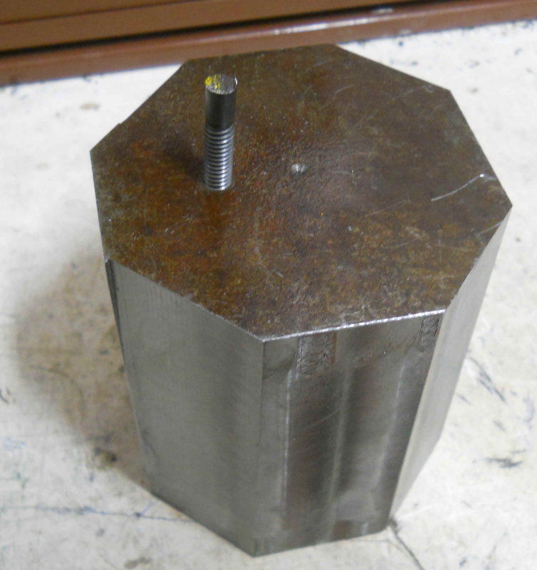
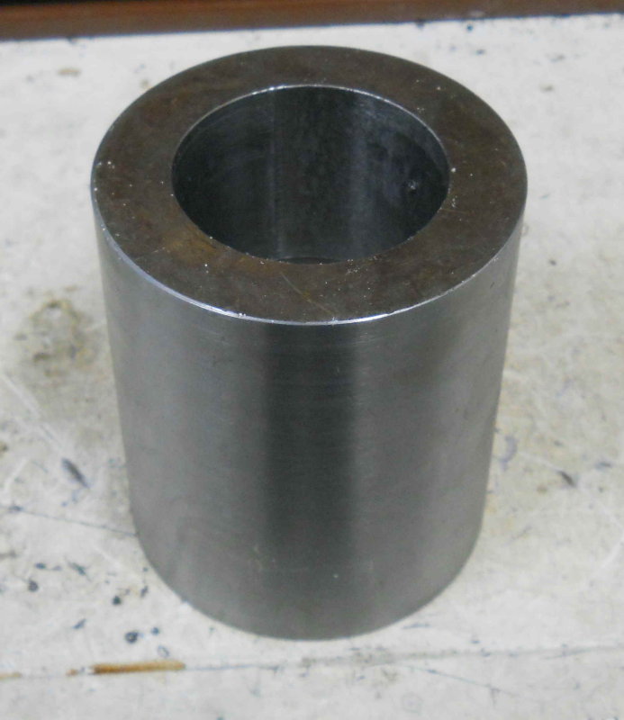
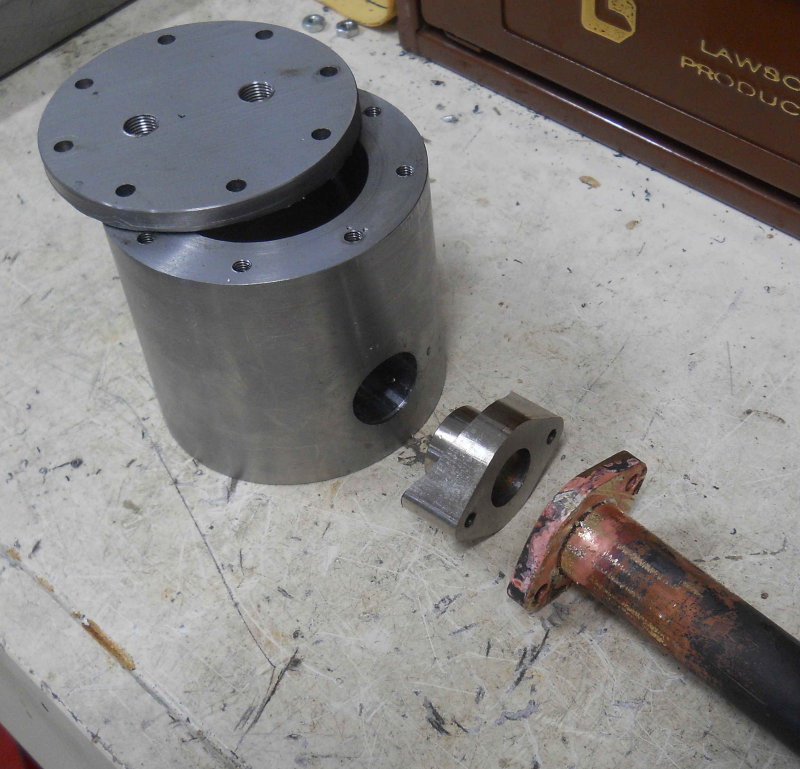
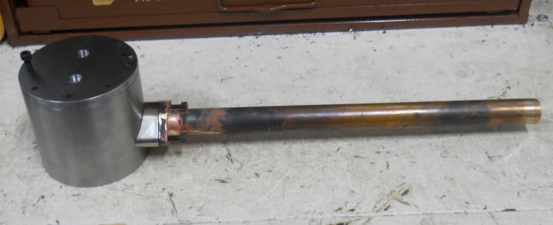
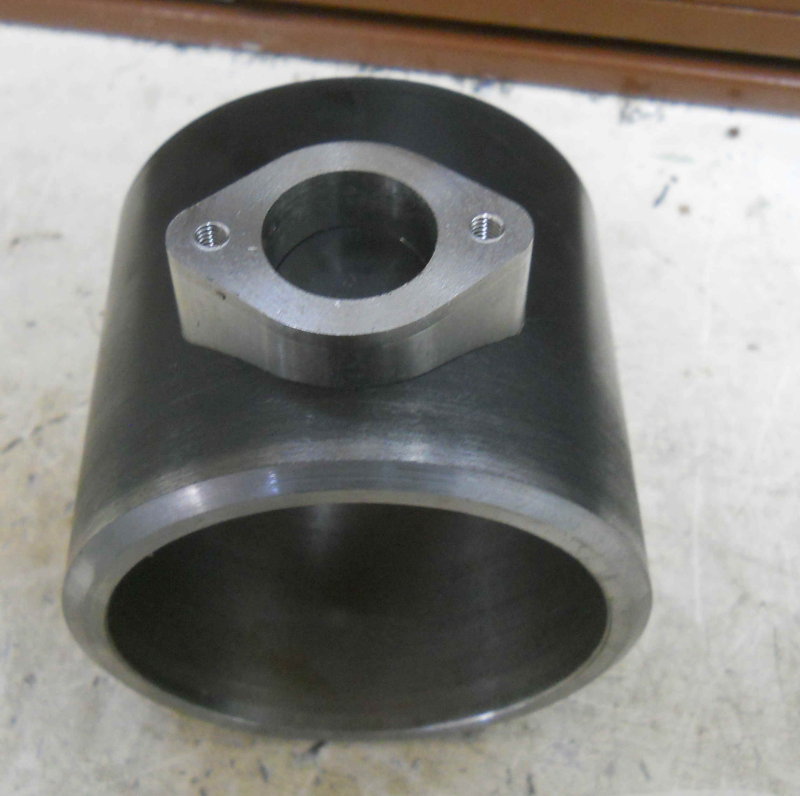
After some more discussion on the steam dome with an experienced builder, I started on fabricating the "can" components that will be welded to the boiler. The first issue was that the flange I had originally was too thin. The tapped holds that secure the cover should not be through into the steam. Therefore I turned the flange off the can leaving a simple cylinder 3.375" OD with a 1/4" wall. Now I need a ring that will be welded to the can to form a 1/2" thick flange 1/2" wide, meaning that the OD will be 2.375".

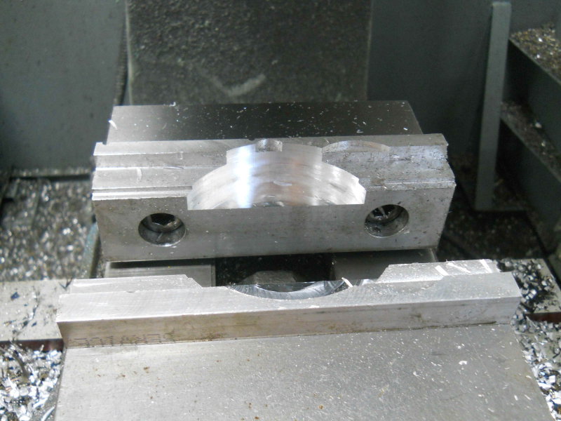
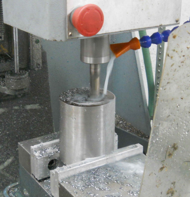
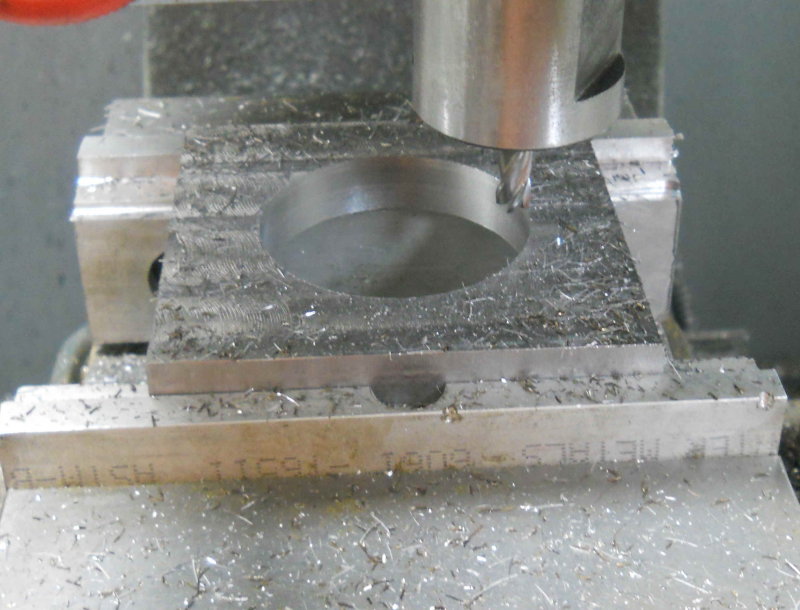
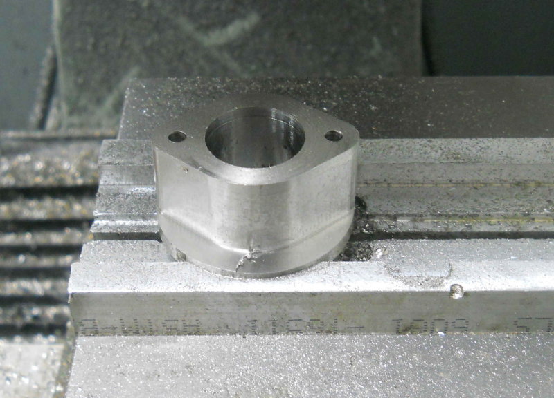
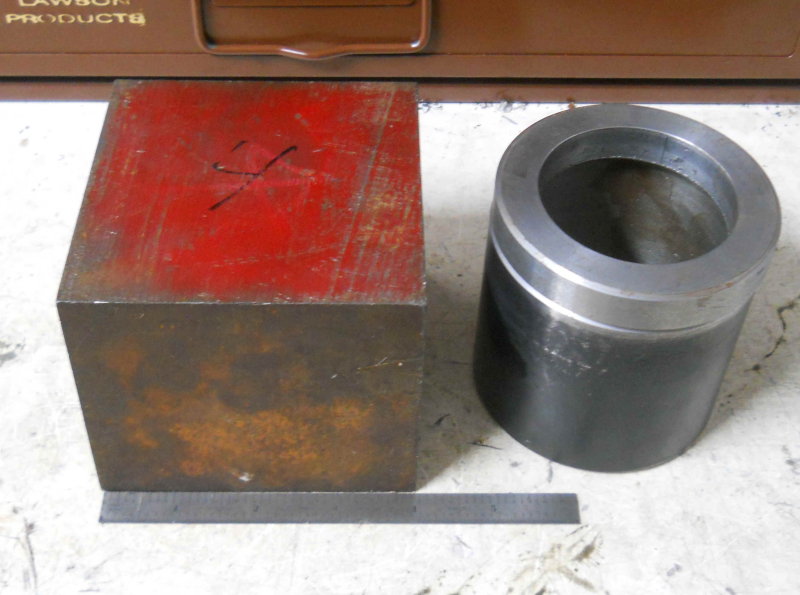
I started with a piece of 5/8" thick HRS about 4" square, faced both faces with a facemill on the manual mill, and milled two of the sides square. Now I could mount the stock on the CNC mill to remove the center material. For this, I wanted to try something new to me. My CAM program allows me to easily draw a flat spiral with any given distance between the loops. So using a 5/16 endmill and a .03" spacing (9% engagement), I would be able to mill at full depth using just the side flutes. This is a type of "high speed machining'. To start, I used a 3/8" endmill to spiral drill a .6" diameter center hole, and then the spiral. A finish circular path brought the hole to its desired diameter.

large.jpg


Total machine cycle time was about 15 minutes.

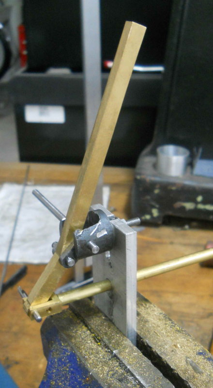
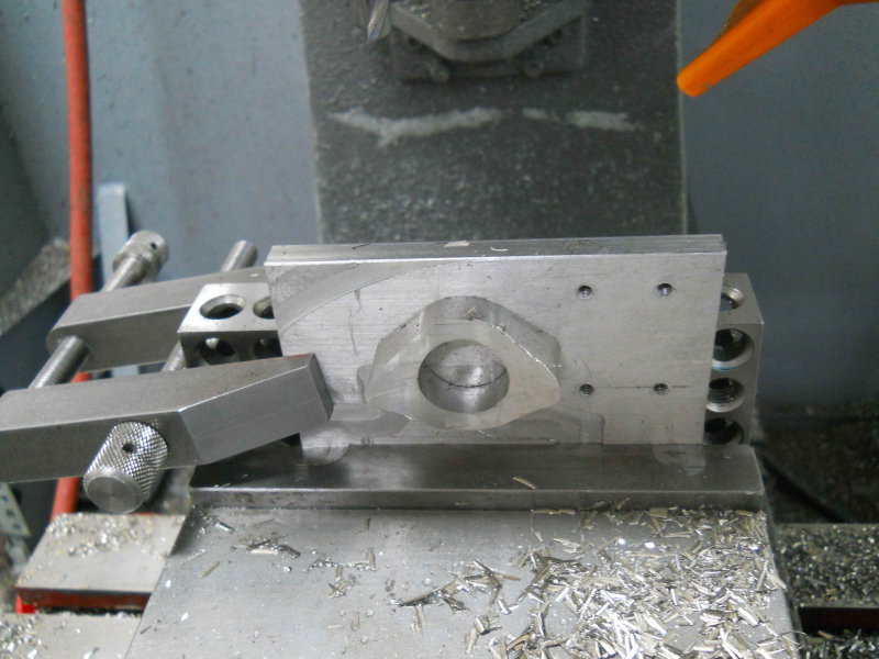
For the OD, I could have programmed a profile cut in CNC, but a large endmill would have cut into the vise soft jaws, and a smaller endmill would have meant a slot depth greater than the tool diameter. So I decided to use the lathe. First I needed to round the corners as much as possible with the manual mill. Here's the setup for the first pass:

large.jpg


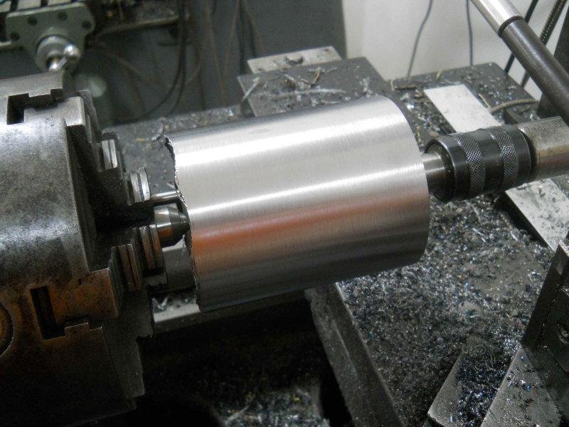
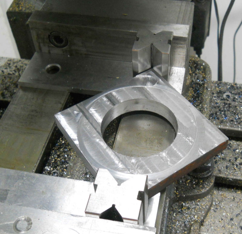
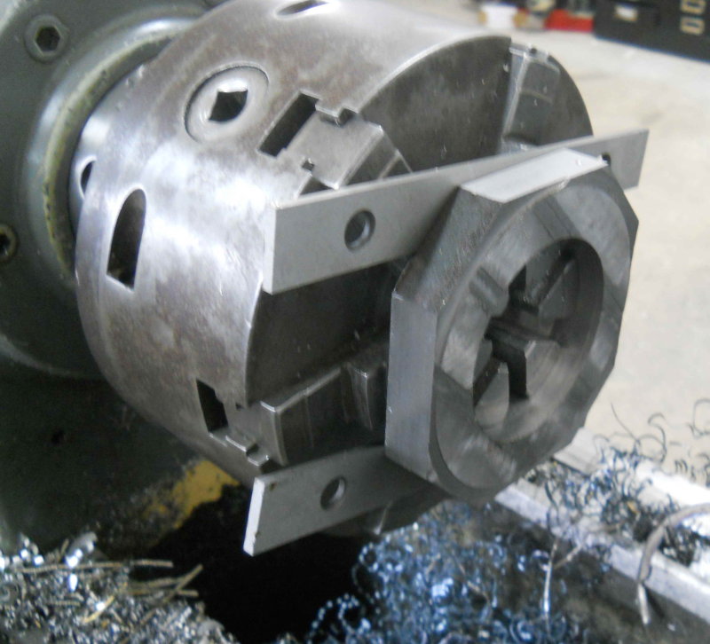
After trimming 4 corners I mounted the work on the lathe as shown here. I used a pair of 1/8" parallels to space it away from the jaws to avoid cutting them.

large.jpg


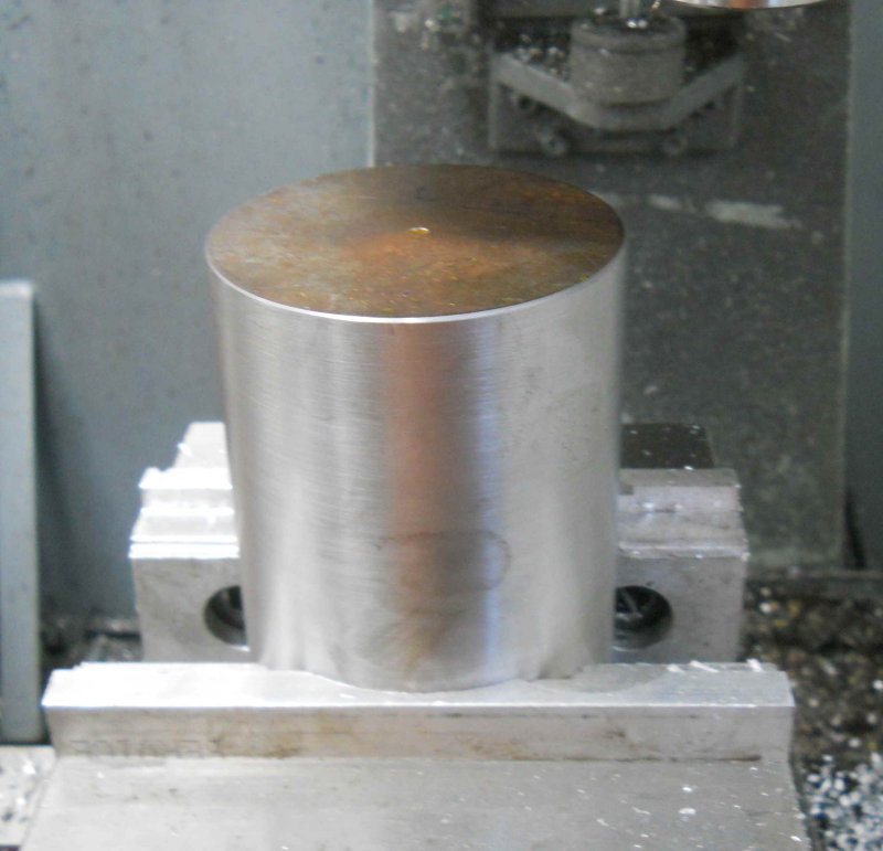
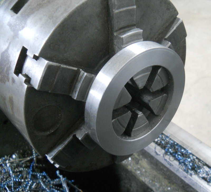
Then I turned it to slightly larger than final dimension, faced both sides, and chamfered one outer edge to allow a space for welding filler.

large.jpg


The cover mounting holes will be drilled and tapped after welding an cleanup.
 
The next part for the throttle is a flange that will be welded to the steam dome "can" and mate with the brass tube/flange. This piece is made with 316 stainless. I started with a 1-7/8 diameter by 1" long round bar, face both ends on the lathe, and through drilled a 5/8" hole.

Then I milled a pocket in the CNC mill soft jaws to hold the bar, and milled the profile and enlarged the center hole to .90". Finally drilled two holes to be tapped 10-32. Here's the result this far.

large.jpg
 
After tapping the two mounting holes, I attached the flange to a piece of aluminum with screws and set up as shown below. Then the back of was milled to match the diameter of the steam dome can.

large.jpg


Here's the piece shown in its approximate position.

large.jpg


I also made a short tube from 316 that will be welded both to the flange and to the inside of the can, making it steam tight.
 
Seems I need to start over on the steam dome canister, so I will make it one piece rather than needed to weld on the flange. I drove down to Metal Supermarkets today and browsed their drops area. I found this chuck of HRS, 4"x4"x3.5" (56 cubic inches). It will be machined into a cylinder with OD 3.375" and ID 2.375" (15.8 cubic inches). So that block is 72% swarf to come.

I could program almost all of the work on the CNC mill, but I don't have endmills that are long enough. So I will likely rough mill the block to a cylinder and then do most of the rest on the lathe. I'm still thinking about the best steps.

large.jpg
 
Wow! That's a chunk of steel alright!

I just received the material for my tender wheels and axels yesterday. Cutting them to size today. But, mines only the 3/4" version. So, smaller pieces. ;)

I look forward to your updates.

Todd
 
Decent progress on my "hunk-o-steel". First op was to face mill 1/2" off one of the long sides to get a 3.5x3.5x4 oblong. Next center drilled both ends for later lathe work. Now milled off the corners lengthwise to get an octagonal cross section. Next drilled and tapped a 1/4-20 hole 1/2" deep in one end, screwed in a SHCS, and cut off its head. Now I had this:

large.jpg


On to the lathe between centers, using the screw shank as a dog driver. Then lots of small interrupted cuts until round, and a final cut to 3.375" diameter:

large.jpg


Back to the CNC mill to cut a pocket in soft jaws to hold the cylinder"

large.jpg


large.jpg


Next session I will use this setup to drill a through hole in the center using a succession of drill from 1/8-1" by eighths. Since the work is 4" long, I plan to run a drill half way, then reverse the work in the vise and repeat the op. Then it will be back to the lathe to bore out to the final dimension.

Alternatively I may use the boring head.
 
The through drilling went fine as foreseen through 5/8" diameter. When I tried 3/4" drill there was not enough torque and the drill stalled the motor (prescribed RPM was 400). I decided to see if I could mill out the bore rather than hand a heavy piece on the lathe with no end support.

Some years ago I bought a lot of endmills online, and there were several > 1/2" in diameter. I found one 5/8" 4-flute mill with 2" flutes, so decided to try that. Using the G-wizard feed&speed calculator, I decided on a .25" radial engagement and a .04" ramped depth of cut, which allowed 1020 RPM and 15 ipm feed. This worked out to be pretty easy on the tool (no chatter), and about 40 minutes to mill 2" deep from both sides.

large.jpg


Here's progress to-date:

large.jpg


The bore is large enough to clear the valve body and the walls are a bit thicker then .5". Any further enlargement can be done on the lathe.

I also went over to visit a friend who offered to silver solder my copper tube/brass flange since he had a turbo torch. Alas, both propane and Mapp gas failed to generate enough heat. I'm going to try it again with the oxy-acetylene torch later.
 
Here's the (slow) progress on the steam dome/throttle. Made the lid, tapped the holes, and bored the hole for the throttle rod.

large.jpg


Mock-up assembly:

large.jpg


Tried to SS the brass flange again today using black flux and my little oxy-a torch, and still couldn't get it hot enough. Arggh! Will try again with the large torch at the club later on.
 
Made a little progress the past few days despite lots of other distractions.

First little job was attaching the number plate to the smokebox door. Soldered a little piece of round brass rod to the rear, drilled and tapped 10-32 to match the door, and attached with a set screw and a ja, nut.

large.jpg


Second task was a complete remake of the reversing bar assembly. The 3/4" scale setup for the latch did not scale well, so I came up with this design for the lever and locking bar.

large.jpg


I'll wait to locate the notches on the quadrant before repainting it.

Final job of the day was making two nuts for locking the crank to the spindle of the throttle valve. The spindle is threaded M6x.05, , not an easy size to find locally where all M6 fasteners at 1mm pitch. It seems to be a good idea to try to use stainless for stuff in the steam dome, so I decided to make two nuts for SS316. I found and ordered a 5.5mm drill and a tap online. Since I had some 1/4" 316 bar, I drilled and machined the nuts on the CNC mill. The nuts will take a 3/8" wrench rather than 10mm.

large.jpg


After freeing and facing to size manually, they do fit the valve.

large.jpg


The fit is pretty loose, whether due to the drill bit or the tap (both imports). They should still work well enough though. I also tremade the crank in 316.
 
Back
Top