Kozo A3 in 1.5" scale

Home Model Engine Machinist Forum

Help Support Home Model Engine Machinist Forum:

This site may earn a commission from merchant affiliate links, including eBay, Amazon, and others.
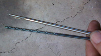
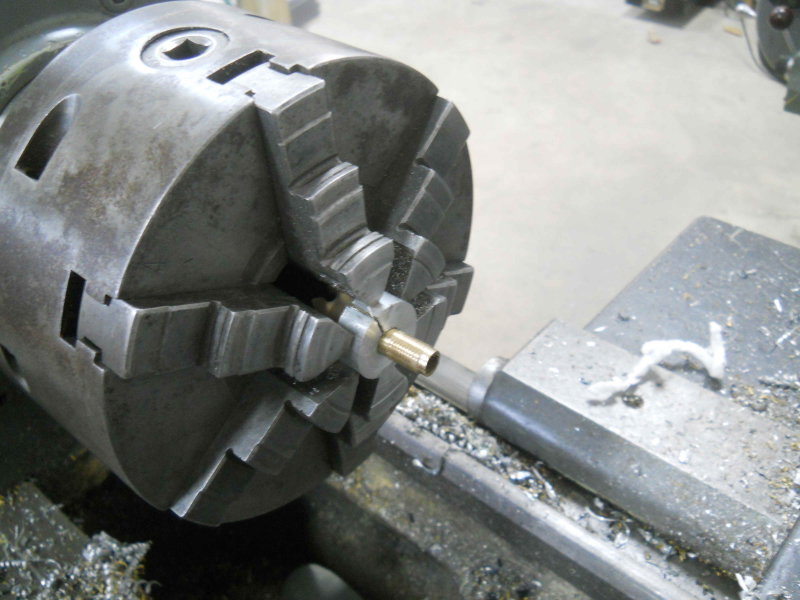
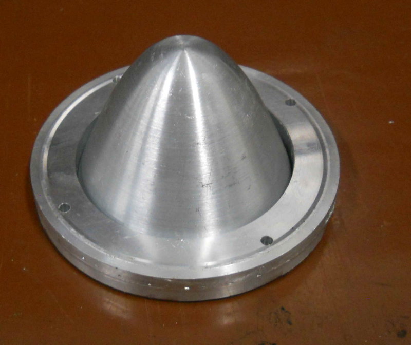
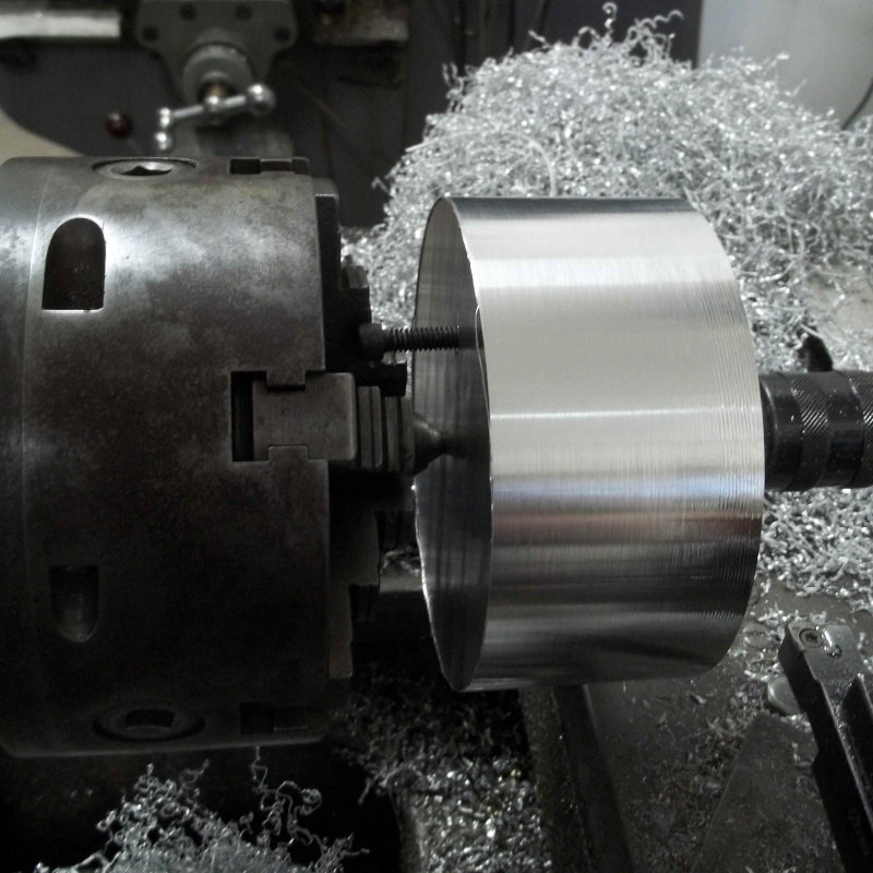
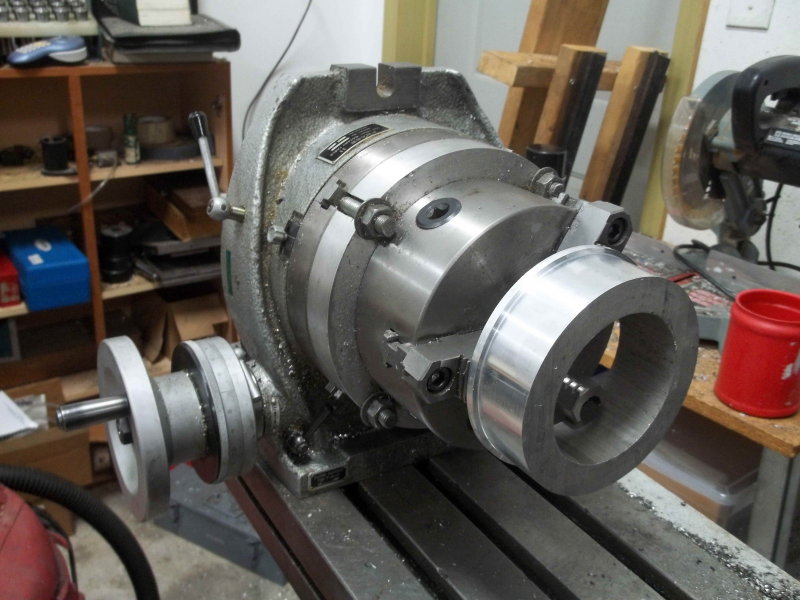
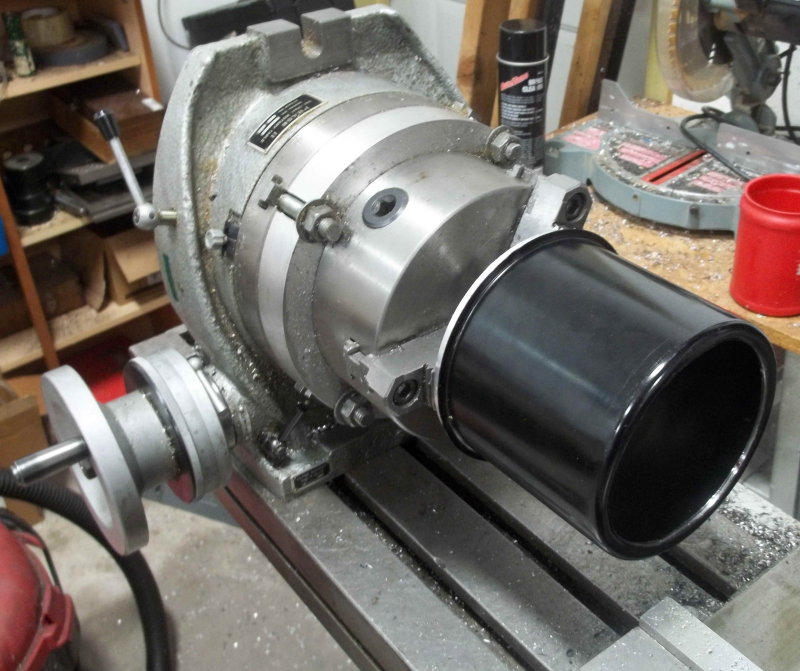
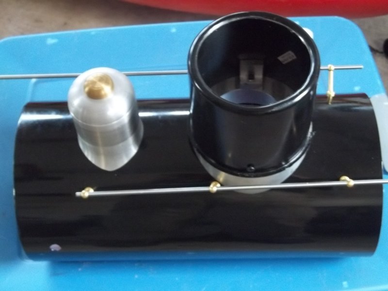
The base of the font (where the glass chimney mounts) is specified to be threaded 3/8-24 to screw into a spigot on the baseplate. However, the diameter of the casting is a bit smaller than 3/8". In any case, I made a little temporary split collet from some 1" aluminum round, mounted it in the lathe, and ran a die over the shaft. Not great threads, but they will suffice to keep the font in place.

large.jpg


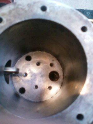
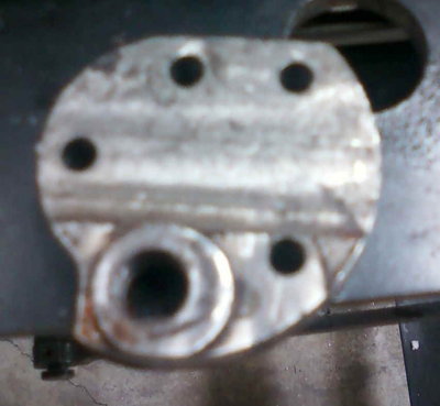
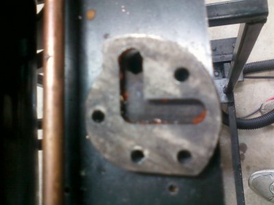
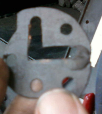
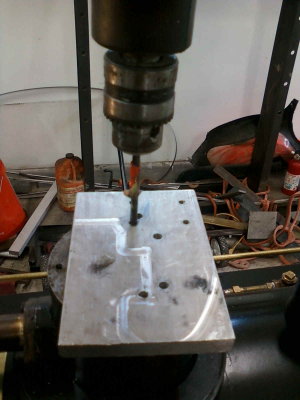
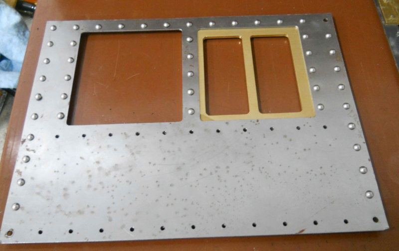
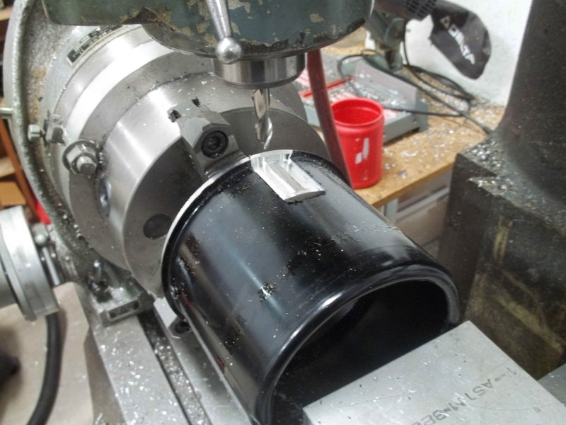
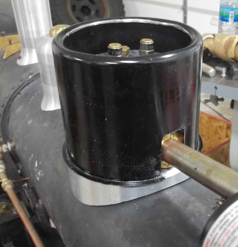
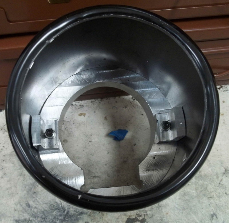
Then drilled the baseplate to attach both to my mounts and to the bottom of the lantern casting. Since the casting will cover two of the mounting screws, the lantern will be attached up from the bottom. Rather than using 5-40 screws in from below, I decided to use set screws in the casting and nuts below.

large.jpg


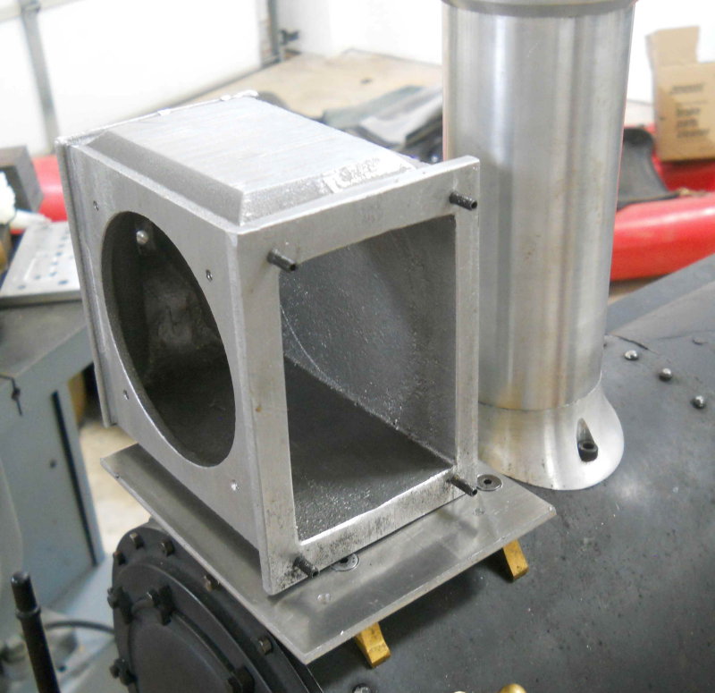
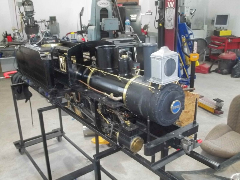
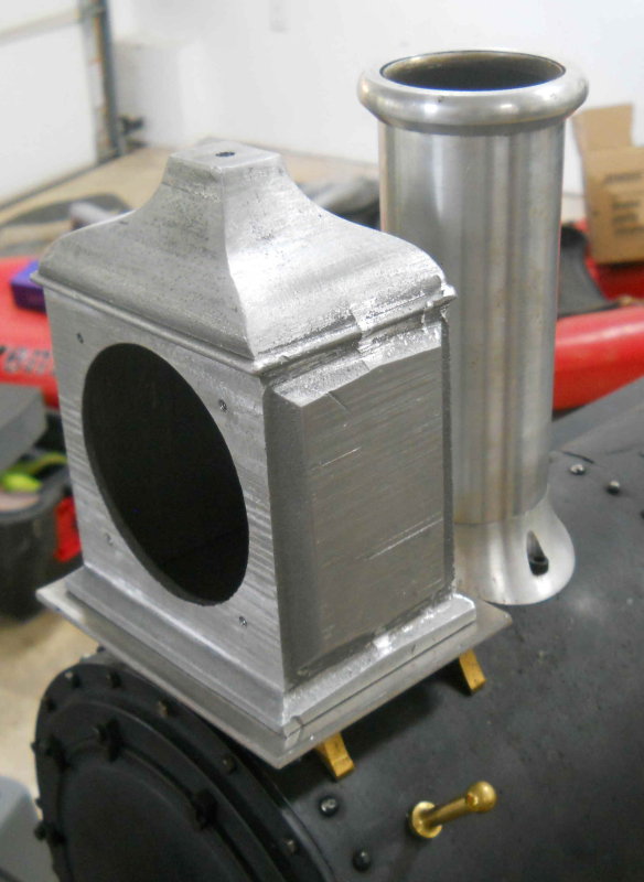
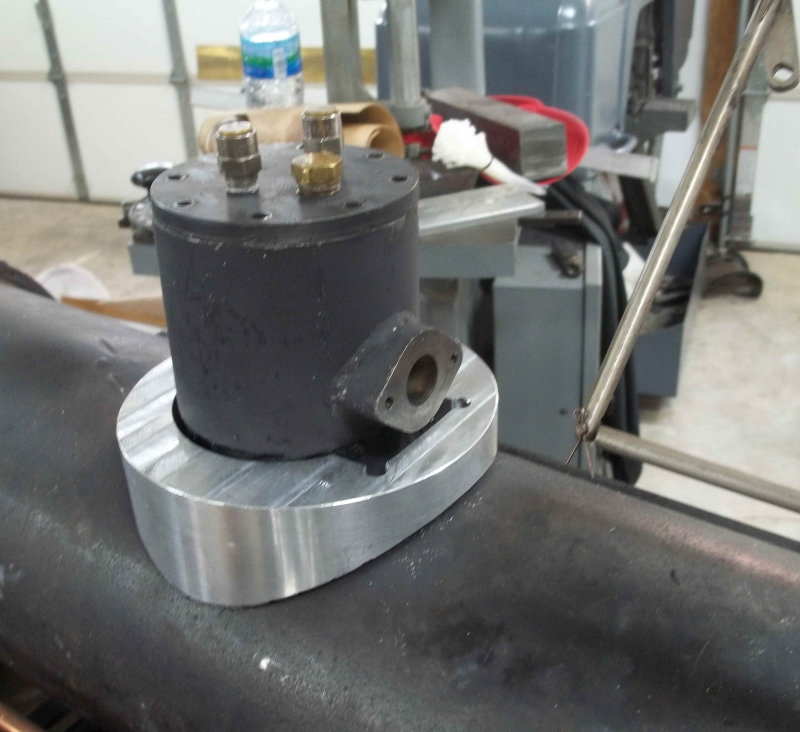
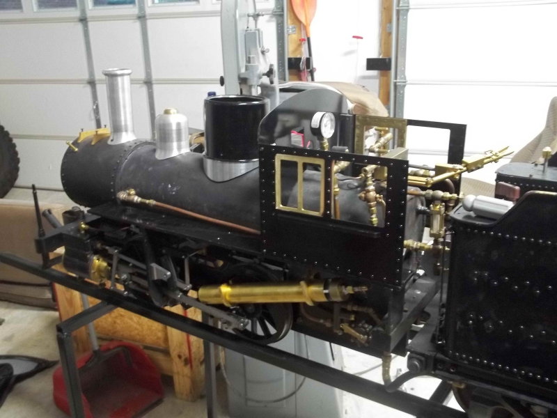
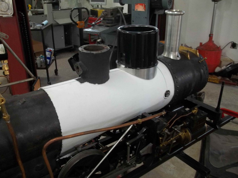
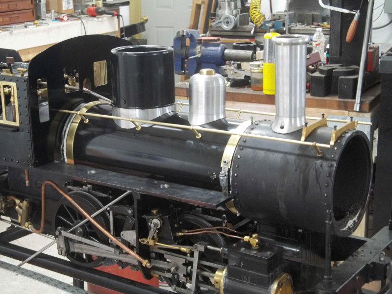
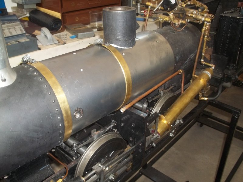
As can be seen, the lantern is pretty large vs. the stack.
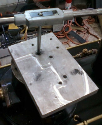
large.jpg
 
Started to work on the reflector, which needs to be polished up a bit on the inside and than have a 3/4" hole drilled to admit the font and chimney. First step was to CNC mill a 2.9" hole in a 4" aluminum coaster.

large.jpg


The hole secures the reflector by its flange.

large.jpg


The reflector is then clamped to the fixture using the bezel casting.

large.jpg


Then I could mount the fixture on the lathe after boring some soft jaws. Now I can spin the reflector while applying emery paper and the like to try to get better reflectivity. Started with some 320 grit. More next time.


large.jpg
 
Electric, probably LED of some sort. One of the club members suggested a part# that I have since forgotten.

Hi

So if you are going to fit a LED why do you need to spend time polishing the reflector?

m8VFacO5WfByvDOT8Qg4PBA.jpg


12V MR16 type 50mm diameter

Pete
 
Decided it was time to finish up the cab. So milled up the window frames for the side-front window and attached them to the sides using #4 drive screws. Frames are made from 1/8" brass sheet and will stiffen up the sheet metal.

large.jpg


I neglected to count the number of holes in the sides and ordered only 1 box of 100 from McMaster. Not enough! So this task will halt until I get another order in.

The heads ( mimicing rivets) are probably a little large for the scale, but they do match the rivet heads in the tender.
 
Having won some free software (Cubify) from a contest on another site, I undertook my first 3D machining part, the base of the steam dome cover.

After purchasing a 2.5" cut from 6" round bar 6061 aluminum, the first job was to reduce the thickness to 2.15" and the diameter to 5.25". I turned it between centers using a 1/4" screw as a lathe dog:

large.jpg


Next, machined soft jaws on the CNC mill to hold the blank:

large.jpg


large.jpg


Next, milled a through pocket to permit the base to slide over the dome.

large.jpg


Then reversed in the vise and roughed the 3D cylindrical surface using a 5/8" 2-flute HSS endmill.

large.jpg


Then did the finish pass with a 1/2" HSS ball mill.

large.jpg


It needed some fitment using the Bridgeport, but now fits well on the boiler.

large.jpg


I still need to fit the cover to the base and paint.
 
Started paint on the cab sides, and while waiting for that to dry worked on the steam dome cover. I am using the center cap of a Cragar 8-lug wheel as the cover. It's the correct size and has a nice black gloss finish. I needed to cut a slot in the bottom for the throttle tube. However, it's difficult to fixture thin metal, so I came up with the following.

I had a chunk of 5.5" aluminum tube with 1" thick walls that I picked up some years back as scrap. I turned the OD down to 5.04" to form a tight sliding fit for the cover. I mounted this on the Bridgeport with the rotary table:

large.jpg


Then slid the cover on and drilled tapped two 8-32 screws into the sides. These holes will be used to secure the cover to the base

large.jpg


Now mill the slot.

large.jpg


And test fit.

large.jpg
 
Test fit of the sides and front of the cab.

large.jpg


I picked up some 20ga sheet yesterday that will hopefully turn into a boiler cover and cab roof in the future.
 
Little more progress. Made two brackets to attach the steam dome cover to its base

large.jpg


Next, started on the boiler wrapper and insulation. Boilers of this size don't normally benefit that much from heat insulation, but in this case the smokebox diameter is 1/2' greater than the boiler tube. So I wanted to pad the boiler so that the handrail stanchions would line up easier between the smokebox and boiler cover.

large.jpg


The material I'm using is a ceramic sheet from McMaster. http://www.mcmaster.com/#93285k18/=pgpafu. Good up to 2300F, so should handle the 350F from the boiler. I ordered the 1/8" thickness, but will use 2 or 3 layers to build up the diameter. It's quite soft and easy to cut with scissors or x-acto knife.
 
I've been working on the boiler casing and associated fittings. After cutting some 20 ga steel sheet to size (21x16"), I got a buddy to cutout the hole for the steam dome with a plasma cutter. Then drilled mounting holes for the sand dome, handrails, and water inlets. Then rolled using a borrowed slip roll.

I'm able to slide it over the boiler taking a bit of care, and then remove it again without creasing. Then I gave it a coat of primer followed by paint (black implement paint from Tractor Supply). Once dry, I installed the handrail stanchions that I bought from Locoparts a while back. They take a 3/16" rail, so I used some 3/16 drill rod for a test fit.

large.jpg


The issue I'll have on assembly is that when the stanchions are screwed down the rails get clamped tight, and I can't adjust them. I also don't know where the power to the headlamp will be located, so if the switch is in the cab I want to run the wire down the handrail. I also want to extend the rails to the stanchions located on the smokebox, and that's likely to be imperfectly aligned.

So my plan is to use brass tube for the handrails. Should be easier to bend where necessary. Need to order some before putting the cover on.

I also bought some 1/16x3/4" brass strip for the boiler bands.
 
Trial fit of the boiler casing today, since I got the brass for the handrails and boiler bands. Getting the casing on was a struggle since the bottom edges would dig into the insulation. I finally tied the insulation sheets around the boiler tube with twine.

The holes for the water inlets are a bit off and will require some filing. I installed the cab and running boards so that I could locate the two holes in the cab front where the handrails pass through.

large.jpg


If I had it to do over I would finish the casing and install it with the boiler off the loco.

I also noticed from the photo that solder joint on the injector steam supply has come undone. argh.
 
After some downtime for the holidays, a bad cold, and a business trip, I managed to get a good fitting boiler cover. A friend cut it out for me on his plasma table from 22ga sheet steel.

large.jpg


Took it off afterwards for paint.
 
Thats looking an awful lot like a locomotive. :)
Thanks a bunch, learned tons in this thread.
 
After fighting a cold for a month, and general winter ennui, I decided to get back into the shop a little and start re-assembling the engine now that the boiler jacket in installed (and painted). First problem encountered was that the throttle quadrant broke apart. if you followed this previously, I originally made it in two separate pieces, but that was too lose. Then soldered them together, but it seems that my solder job was poor. So I decided to make it from a single piece of brass.

First op was CNC machining the gear teeth profile. Final pass was 3/64 2-flute endmill, my smallest:

large.jpg


Then a bunch of manual ops on the Bridgeport to get to the final shape (sorry for the fuzzy photo):

large.jpg


Then installed:

large.jpg
 
After painting the boiler jacket and getting it back on with its bands, I started to reassemble everything I removed to install the jacket. Plus I could install the steam dome, sand dome, cab front/sides, and the handrails. My steam feed tube to the right side injector is fubar, so I'm waiting for a couple of new unions to remake it. I also added a second notch on the reverser quadrant to see if notching up will help reduce steam consumption.

large.jpg


From the following photo you can see that the headlamp still needs work and that I messed up aligning the stanchions on the boiler with those on the smokebox. Plus my painting is crap. I did remake the number plate engraving the numbers much deeper (.06). The first try was only .006 deep and the background got scratched up right away.

large.jpg


I need to take it out to the track soon for some solo practice keeping the water and fire both going for more than one loop around the yard.

One problem is that the injectors are too far inside the edge of the running boards so that I can't see the drain pipe. I am making a jury-rig system with an elbow and a piece of brass pipe to stick out beyond the running boards. An alternative would be to cut a window in the part of the boards that are inside the cab.
 
So a month ago I took the loco to the club for the annual hydro (its second). Fail! Cylinders full of water and no pressure. Pulled the steam dome cover and the throttle valve was closed, so I had to assume that the valve's mounting plate had gotten loose. Sure enough, two of the 4 screws that hold it to the boiler were loose, as if the threads were stripped. Took the loco back home where it's sat for a while. I couldn't think of a better or easier way to mount the valve, so today was time to fix it.

Originally I'd tapped the 4 mounting holes 8-32, mainly because that was the only size of SS screws I had. I figured that the steam pressure would press the mount down anyway. Here's the view inside the dome:

medium.jpg


The large hole is the pipe to the clyinders, and the two rear holes are open to the boiler. The mounting plate sits on the bottom in this orientation, held by 4 screws. The large hole is where the globe valve screws in.

medium.jpg


The underside of the plate has a channel connecting the valve to the steam pipe.

medium.jpg


Looking at the gasket reveals the problem.

medium.jpg


To make the plate more secure, I decided to drill out the tapped holes and re-tap to 10-32. Problem is that the dome is 3" deep, and my drills and taps are less than that. Checked out McMaster for a 6" #21 drill bit and 10-32 tap:

medium.jpg


To ensure drilling and tapping straight, I used some scrap aluminum bar with two tight fitting holes for the drill and tap. Marked the drill with some tape to get the holes 3/4" deep.

medium.jpg


medium.jpg


Off to the hardware store to find some SS screws then a new gasket, and we'll see if it will pass.
 
Back
Top