Kozo A3 in 1.5" scale

Home Model Engine Machinist Forum

Help Support Home Model Engine Machinist Forum:

This site may earn a commission from merchant affiliate links, including eBay, Amazon, and others.
Did a few things preparatory to trying another steam up.

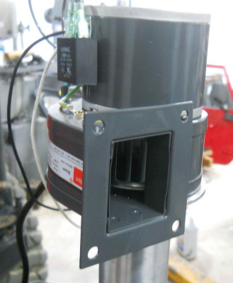
I had borrowed a blower for the stack from another club member, but I need to have my own. So found this Dayton exhaust blower on eBay for under $40 shipped:

medium.jpg


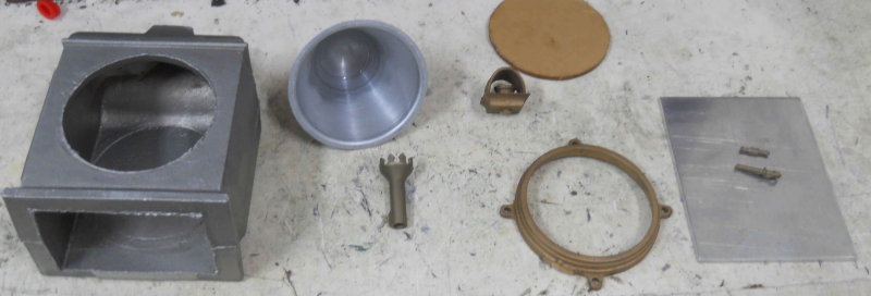
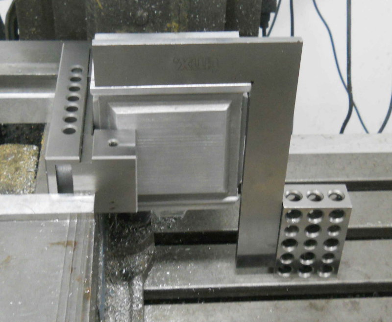
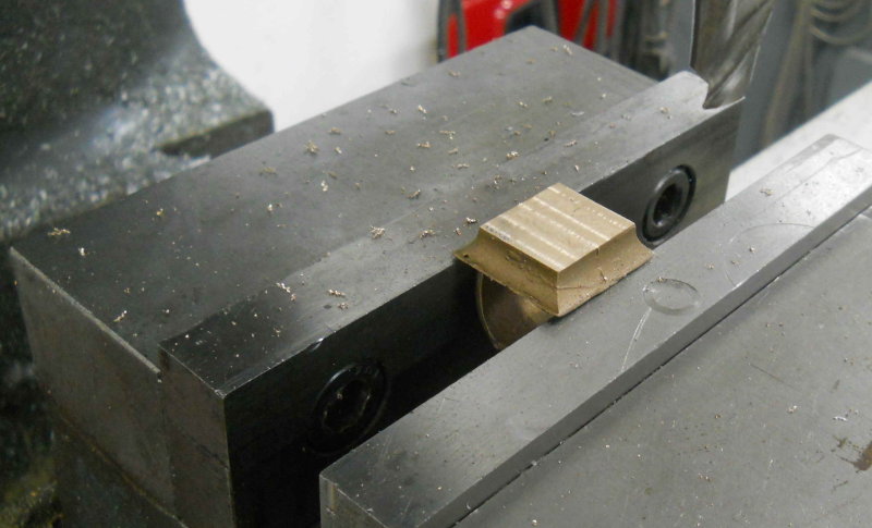
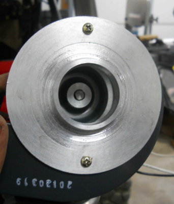
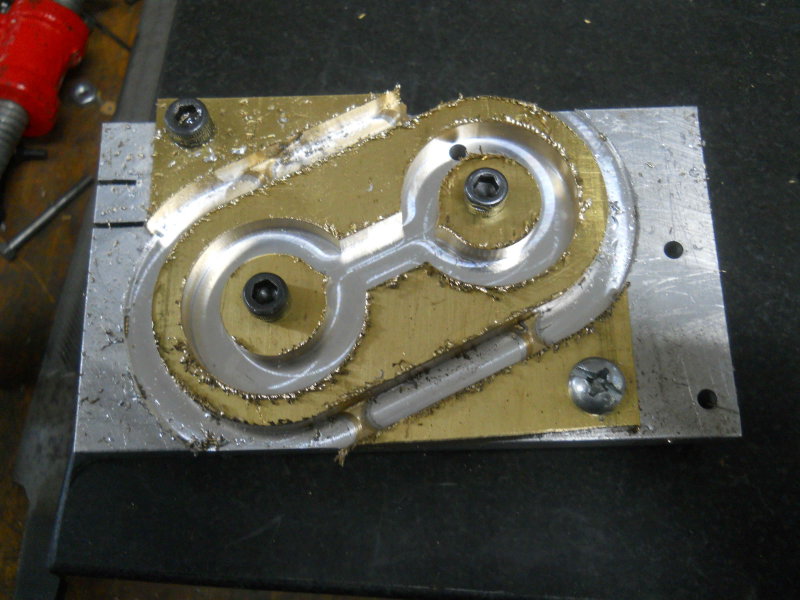
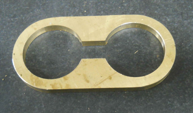
To have it sit securely on the stack I turned down a scrap aluminum coaster to have a spigot that fit the stack, then bored out the center to 1.5":

medium.jpg


Then wired to a 3-prong plug/wire from an extra PC power cable, and it seems to move a decent amount of air.

Another needed tool was a rod to clean flues. For the brush portion I bought a 3/4 inch "fixture brush" in the plumbing section at Lowes for $3, then used the bench grinder to grind the bristles down to a "not too tight" fit to the flues. After cutting the handle off, I made a steel ferrule and welded the brush shaft to it. Other end of the ferrule was tapped to screw onto the SS rod. Finally turned a simple handle from aluminum and used Loctite to fix it to the rod:

large.jpg


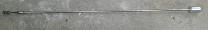
The rod is 3/16" diameter and flexible enough to do all the flues except the bottom center one from the smokebox. That flue will need to be cleaned from the firebox end.

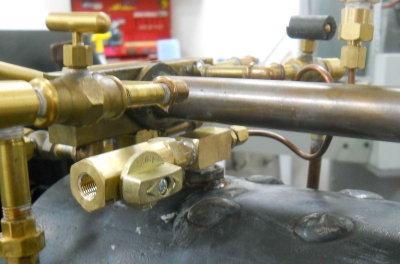
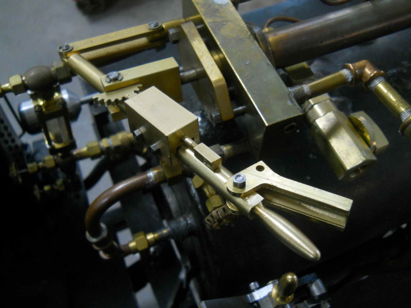
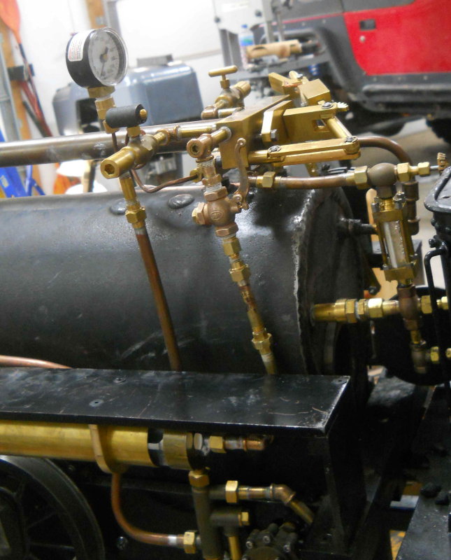
The other mod was to use a T fitting for the pressure gauge plus a ball valve. The valve when open vents the boiler when filling with water. It can also be used to vent steam at the end of the day, possible for steam cleaning the loco itself.

medium.jpg
 
I haven't spent a lot of time on the loco for a while, but today made a quadrant for being able to lock the throttle in place.

large.jpg


Now I need to figure out a spring-loaded handle and mechanism to engage the teeth of the gear. I've seen a few examples in the past. With the present throttle geometry there are 4 positions between closed and full open.
 
Next step in the throttle quadrant is the lever to be attached to the bar. Played around with various options in CAD and came up with this. First cut the profile with the CNC mill:

large.jpg


Then manual milling to get to this:

large.jpg


That was all for today.
 
Continued work on the throttle lock the past couple of times in the shop. Here's all the pieces:

large.jpg


Then took the plunger to the CNC mill to profile the end to match the quadrant gear:

large.jpg


The square end of the plunger is 3/16" and the endmill is 1/8. Then a bench assembly to test the "action".

large.jpg


The handle and plunger were connected with some solder wire as a temporary test. On the loco I will use some stiff wire. The spring is salvage from a ballpoint pen, and seems just the right force. Cheap to replace if it wears out.

Installed on the throttle bar I have a problem. The quadrant gear is not a tight enough fit to the clevis resulting in quite a lot of slack in the throttle position. I think soldering it to the clevis is the best solution.

large.jpg
 
Greetings,
In regards to your stak blower; I did the same thing for my steam traction engines. Make sure you have some fresh air coming in at the stak or you will melt down the squirrel cage from the intense heat from the boiler as I did. The cage got sooooo out of balance that I had to discard that one and replace it. At first I just put a wedge of wood into the stak along with the blower. Then I made an adaptor from duct work that bolted to the blower and fit snuggly into the stak. I punched ten 1/4" holes around the perimeter to draw in cooler air to tone down the hot gases coming from the boiler. Awesome job on the loco !!
Regards, Larry
 
Last two shop sessions were devoted to machining the steam whistle. This is from an old Locoparts kit that I bought from a fellow club member. If you were to buy this whistle today it would be already machined with a cast brass core rather than the aluminum I have. In any case, it was necessary to machine the center casting and the brass "cup" to fairly precise dimensions. Here's the parts prior to assembly:

large.jpg


The casting diameter needed to be a press fit to the 1/5" OD brass tube, whose ID I measured as 1.435".

Assembled, it looks like this:

large.jpg


Here's the approximate position for mounting under the left running board. Obviously I have to clear the lifting link.

large.jpg


Locoparts sells a 6" long model that might be a better choice for small engines, but I think it will fit. Next session will be to fabricate some mounts for it.
 
I started work on brackets for mounting the whistle under the running board. Started with some brass, 3x4x1.4" and mounted on a fixture place. A bit of CNC milling to get this:

large.jpg


Removed from the plate, cut off the holding tabs, and cleaned up:

large.jpg


Then sliced in two with a slitting saw:

large.jpg


Then test fit on the whistle:

large.jpg


Next time out I'll drill/tap the brackets for some 8-32 screws, and then drill the runnijg board. I also mocked up the whistle valve position, so once I can hold the whistle in position I can pipe the valve to it.
 
Third try at steaming up today. I still had a little trouble getting the fire to stay lit at the start but finally got it going pretty well. At 60 PSI I gave the new whistle a try with "mixed" results:

[ame]http://www.youtube.com/watch?v=iKzGCouVTg8[/ame]

As can be see from the comments, the whistle valve stuck open meaning dump the fire and pressure. Fixed the valve (hopefully) but it was too darn hot and too little time to fire up again today.
 
Last edited:
As can be see from the comments, the whistle valve
stuck open meaning dump the fire and pressure. Fixed the valve (hopefully) but it was too darn hot and too little time to fire up again today.

Shame, that. I've only made one loco but have valves to cut out most every line including the brakes, whistle and both water lines (valve after the check - if the check sticks I can cut it off, fix it and return to service.
 
A friend discovered that the whistle valve was installed in the wrong direction, so that the steam pressure opened the valve. I reversed it and that solved the problem.

I still failed to get around the yard more than 1.5 times before losing both the fire and water. Too many things going on at once for a beginner engineer, plus the tiny firebox door is a problem for feeding the coal. The injector position is also a problem as it's very hard to see from the tender with the running board in the way. In the steaming bay I have no problem getting the injector to feed water, but whether I can make enough steam to drive it and the loco at the same time remains a question.

I'm thinking I might move the injector above the running board. It should lift that high, but the water intake would be above the bottom of the tender.
 
I brought the loco home this week after sitting at the track for a couple of weeks. Today I gave the steam dome and its top a coat of hi-temp paint, and the top was starting to get a bit rusty. Of course I should have painted it right after it was welded on.

I also decided to break the grate into two pieces vs. the single piece grate Kozo designed. It's to hard to get in/out and awkward to dump the fire.
 
Did a bit of shop time the last few days, including starting on the headlamp. Rather than build one per Kozo's book, I bought a casting kit from Railroad Supply. It will be a good deal larger than the plan, but the result will likely be better than I'd do on a scratch build.

Here's a look at the parts as delivered:

large.jpg


Cleaning up the aluminum case casting is the biggest part of the work. In order to true up the sides and bottom, I used the back as the initial datum as it was quite flat and smooth. Holding it in the vise presented some challenges because of the odd shape. Here's the setup I used to mill the bottom as well as drilling/tapping 4 mounting holes:

large.jpg


The lens provided is a round piece of 1/8" thick lucite. It was about .04" too large in diameter to fit the cast bronze frame, so I had to file it down a little at a time until it made a good tight fit. With the frame mounting holes drilled and tapped for 5-40 screws, a little test fit was in order, including the aluminum reflector.

large.jpg


The reflector is parabolic and should project a fairly tight light beam, esp, with some polishing.

large.jpg


The chimney vent is a bronze casting that will require some filing. It's attached to the case by a 10-32 acrew, so a hole in the center needs to be drilled and tapped. It was difficult to hold very securely in the vise, so I milled the bottom flat using .01" DOC and feeds on in the y direction.

large.jpg


Test fit of the vent on the case:

large.jpg
 
Calcium carbide is hard to find these days, but it does give that authentic glow. :)
 
Back
Top