Jan Ridders Horizontal Stirling "Bas"

Home Model Engine Machinist Forum

Help Support Home Model Engine Machinist Forum:

This site may earn a commission from merchant affiliate links, including eBay, Amazon, and others.

rhitee93

Project of the Month Winner!!!
Project of the Month Winner
Joined
Mar 13, 2012
Messages
583
Reaction score
62
This is a build log for a horizontal Stirling engine designed by Jan Ridders. There are a number of these engines that show up when you do a search on this site. I don't think mine will be much different than the rest, but I'll try to capture the process as I go along.

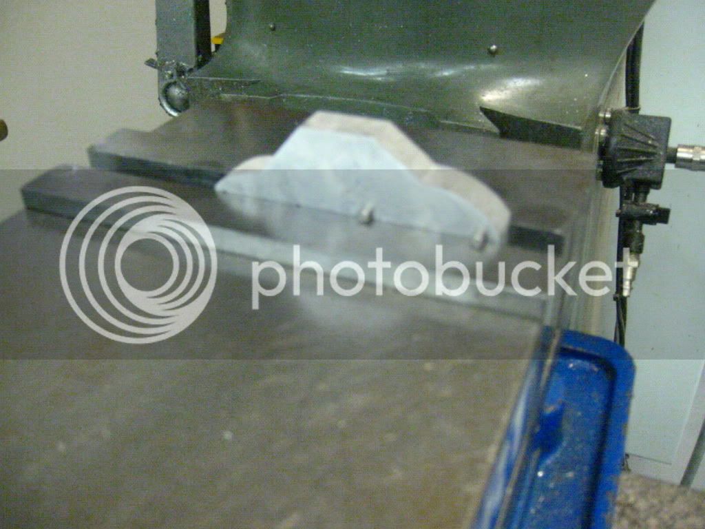
I got a start today by waterjetting out a blank for the cylinder mounting block. This isn't the ideal tool for the job as I'll demonstrate later, but I don't have a rotary table, and my programming ability on the CNC mill is quite limited.

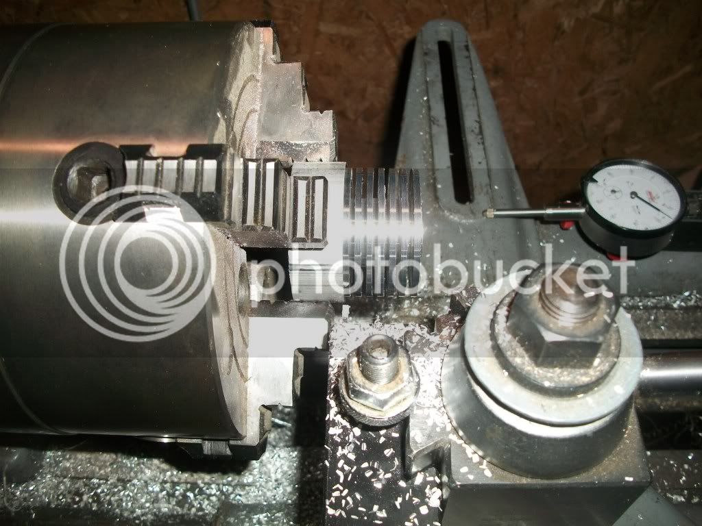
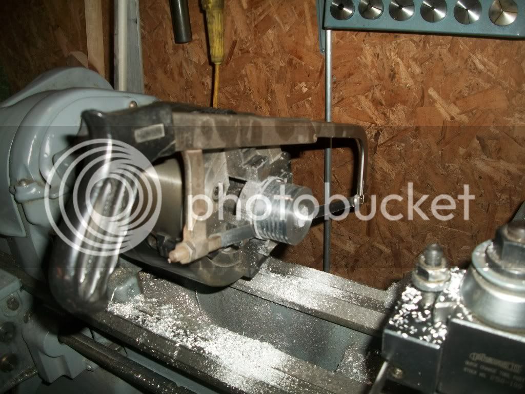
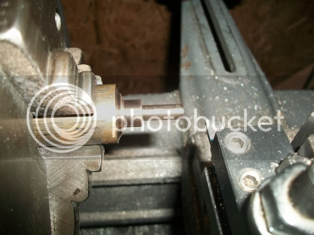
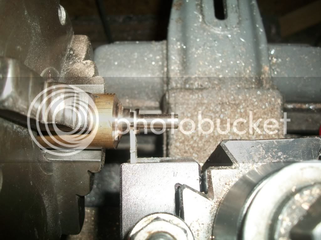
After I had the blank, I clamped it up and fly cut it to the correct thickness. (Sorry for the out of focus pictures. I used a different camera than normal, and couldn't see the photos were out of focus until I put them on the computer)

IMG_4594.jpg


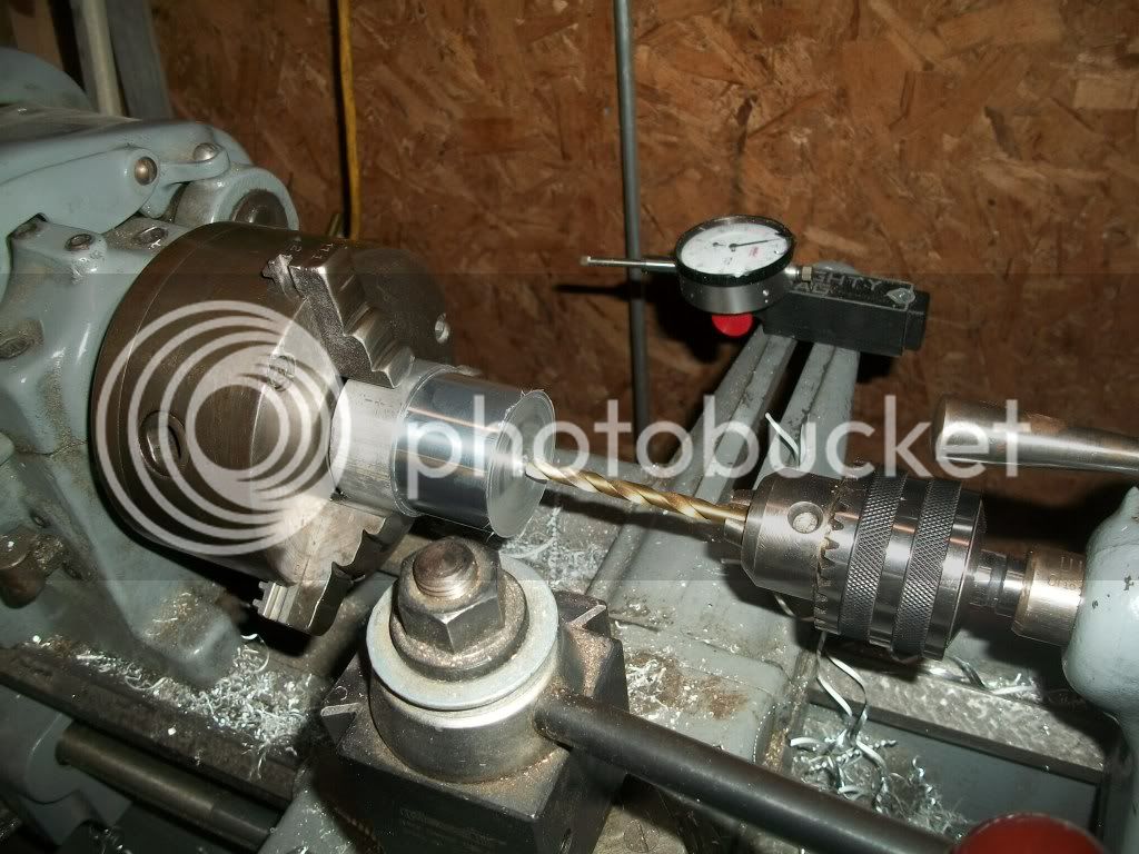
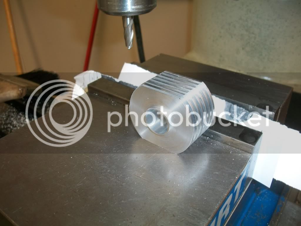
When I cut the blank, I made and undersized hole for the displacer cylinder and more undersized holes for the cylinder flange screws. The plan was to use the mill to cut these holes to size and to accurately locate the blind hole for the power piston. To do this, I had to make a fixture to clamp the part to.

IMG_4595.jpg


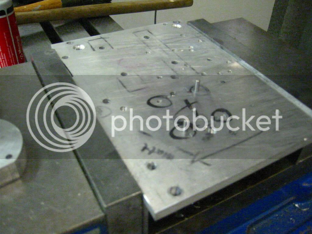
The fixture is just a well used plate of aluminum with the bolt pattern for the displace cylinder flanges drilled. I reamed two of the holes to accept dowel pins, and tapped the other two for 4-40 screws. With the pre-cut holes in the part reamed to slip over the dowel pins, I had a securely held part with a known location.

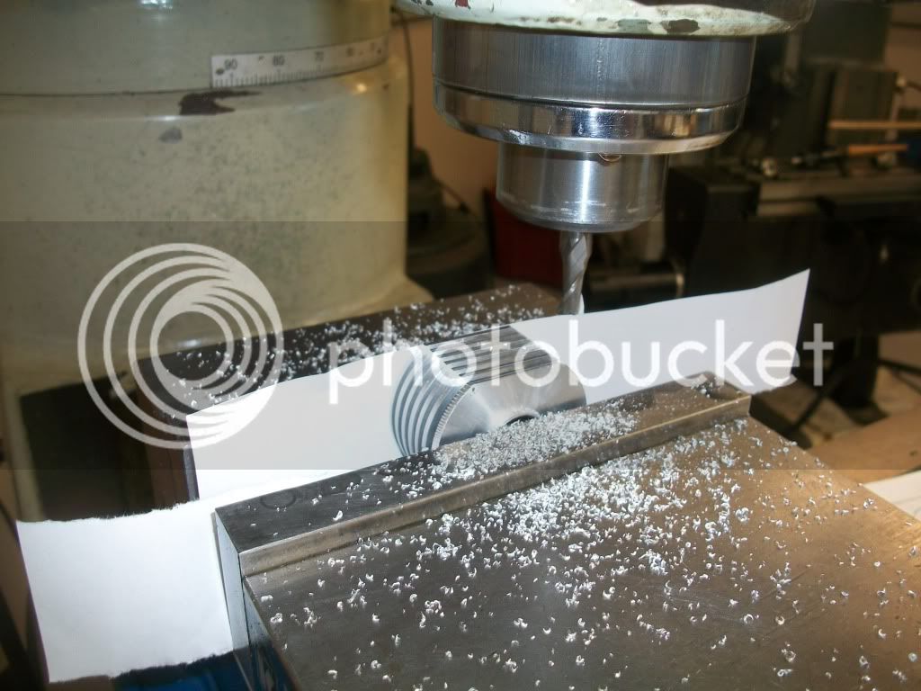
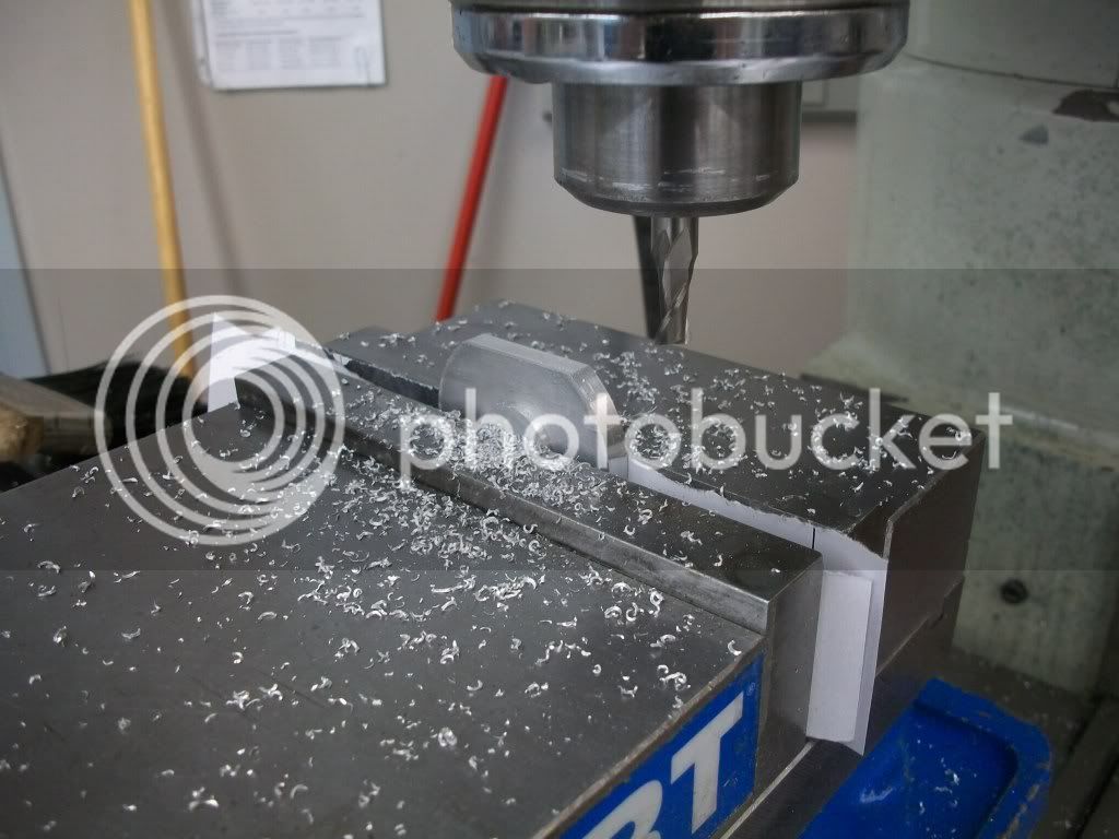
Then I milled in the hole and pocket for the two cylinders. I could have used a boring head, but programming in a circular pocket ins one of the few things I know how to do with this machine.

IMG_4598.jpg


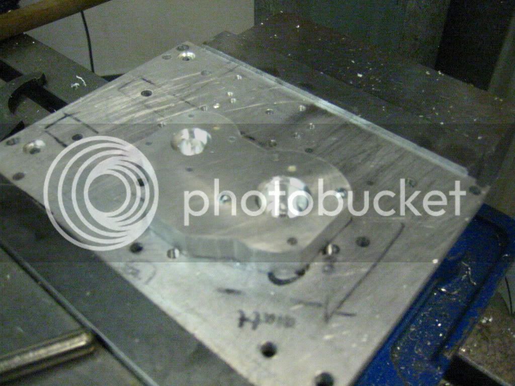
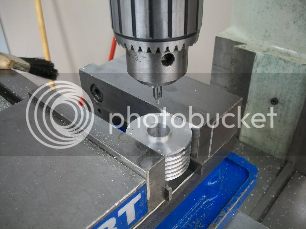
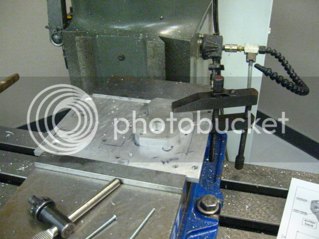
To locate the pocket that surrounds the displacer hole on the other side, I simply flipped the part over and rotated it 90 degrees so that it would slip back down over the dowel pins. I had to use a clamp to hold it down this time because the bolt pattern is actually a rectangle, not a square so the threaded holes don't line up after the rotation.

IMG_4599.jpg


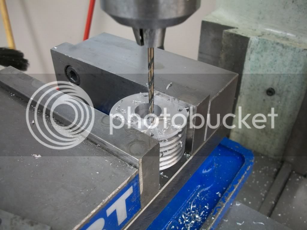
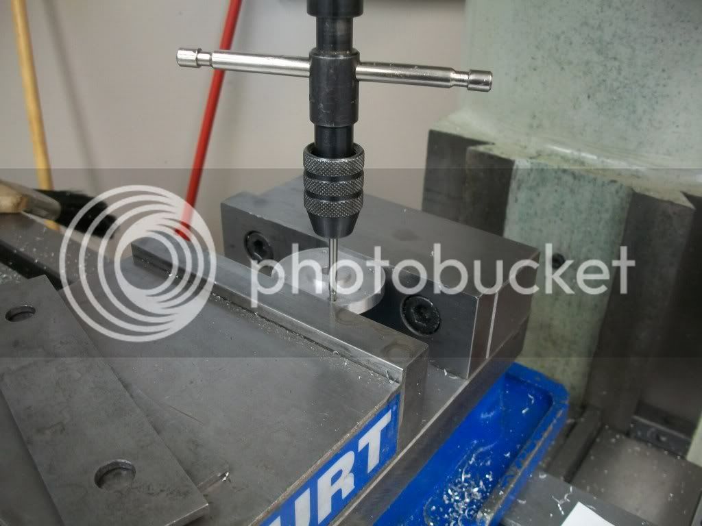
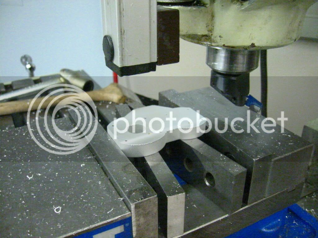
I needed to find a way to clamp the part back in the vise so that the centerline between the cylinders was horizontal in order to mill the notch in the bottom that will accept the mounting bracket. To do this I put the dowel pins through two of the mounting flange holes and let them rest on top of the vise. I used this trick again with two different holes to drill the air passage between the two cylinders.

IMG_4600.jpg


Now the problem with a waterjet is that the edges of your part have what is essentially a media blasted finish. We use 120 grit abrasive in our machine, and the edges come out uniform, but with a heavily textured finish. This is a bit of a pain if you want to have a polished finish in the end. (Yeah, I know. You guys all feel sorry for me now :) )

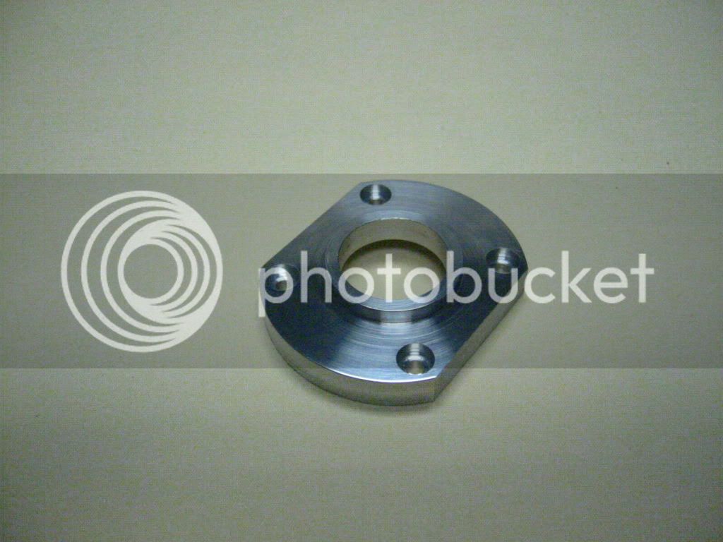
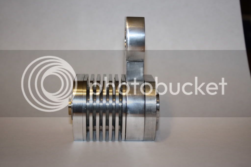
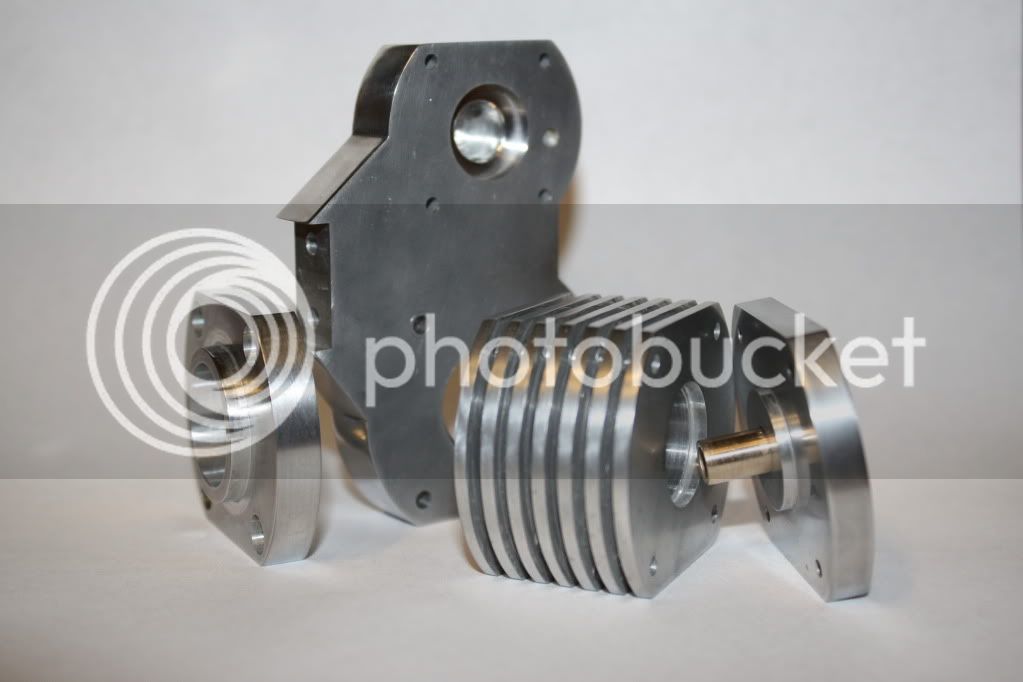
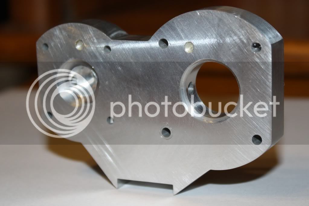
An hour and a half with a file and then successive wet sanding got me to this. This is to 400 grit. I'll have to go a bit further to get the level of polish I want.

IMG_1898.jpg


Well, that's all for now...
 
I got a little more done on this engine over the weekend. I bought a slug of 1.125" aluminum to make some of the bigger parts from. I cut off a 2" piece using the big horizontal bandsaw at work so I could turn the cold cylinder. First I chucked it up and turned it to the right OD (52mm in this case) and faced the end off:

100_2094.jpg


Then I center drilled the end and drilled through with a 1/2" bit. (This is the largest bit I have)

100_2096.jpg


After that I started boring out to the correct ID. This is when something strange happened. On the last pass I dialed in to take about 3 thousandths off the radius and ended up taking off about 10! I am not sure what happened. I do a lot of boring with this lathe, and know it pretty well. I had the compound cranked over at a funky angle from some other operation. I wasn't using the compound for boring, and I wonder if some residual backlash came out of it on the last pass. As soon as the tool hit the part I knew I was pooched :(

100_2097.jpg


Since I overshot the cold cylinder bore by quite a bit, I decided to turn this piece into the flange that hold the hot cylinder in place. So I kept boring to the right ID (No issues this time :) ) and used a parting tool to cut the boss in the end.

100_2100.jpg


Then I parted off the piece and flipped it around to cut the o-ring gland on the back side.

100_2105.jpg


somehow I missed getting pics of the milling and drilling ops to finish the part off, but here it is waiting for final smoothing and polishing:

IMG_4606.jpg
 
I cut another slug off my aluminum bar and started on the cold cylinder again. So here we are turned to diameter. However rather than go at it with the 1/2 drill, I drilled and bored a 7mm hole. I figured it would be smart to cut the cold cylinder and it's end cap from the same bar so the diameters would be matched. The 7mm hole is for the displacer rod bushing.

100_2108.jpg


Then I turned the boss for the end. I made this a standard size to fit my fractional collets rather than the metric dimension in the prints so I could flip it around for the finishing ops later on.

100_2109.jpg


Now I knew that I wouldn't be able to use a parting tool this deep, so I went as far as I could and used a hacksaw the rest of the way. I didn't get very far with the parting tool. I'm going to have to regrind it now :rolleyes:

100_2112.jpg


After the part was off, I refaced the piece in the chuck and drilled for 1/2" again.

100_2114.jpg


Then I bored out the 17mm diameter bore. I even got it right this time :)

100_2116.jpg


This is where the part will spend the night. I ordered a parting tool the right width to do the 2mm spacing for the fins. I should have had it before the weekend, but it fell behind something on the truck and got missed by the driver. Hopefully I'll have it tomorrow.
 
Hi Brian

I looks like you are off to a good start on your next engine.

Just a matter of curiosity what is the controller on the CNC you have?

Thanks for the update on your new project.

Dave
 
Dave, the CNC mill is one at work. It is a Bridgeport with an EzTrack controller. From what I understand, it is not a very popular controller in the industrial CNC world.

I got a little bit done on the cooling fins for the cold cylinder tonight. each of these cuts is about 0.080" wide and almost 1/2" deep.

Bleah! It is slow going. The more astute may notice that the part is now in my 4-jaw. Part way through the first cut the tool got stuck, and caused the part to shift in the 3-jaw. The big old flat belt on this lathe is a bit loose, so when something like that happens it tends to slip and gives me time to shut it down before I break anything. In this case I was able to clock it back in and keep going.

100_2117.jpg


The even more astute will realize I am going to run out of finished cylinder before I get two more grooves cut. When I sized the blank up, I mis-read the print and forgot that the 2mm long boss on the end wasn't in the 26mm length. This means I am going to come up 1 ring short, but I think I can fix it. I may have to move it in the chuck again. This seems to be a demon possessed part intent to keep me making mistakes :wall:
 
Well, we left off last night with the fins partly cut and a blank that was a bit too short. Tonight I cut the last two grooves and then squeaked out another fin before running out of room.

100_2119.jpg


There was no room left to try to make any of the parting cut with the lathe, so I had to use the hacksaw for all of it. Let me tell you, when you weight a buck-thirty-five, and have the upper body of a school-girl, this takes a while.

100_2120.jpg


Then I turned the part around and opened up the bore for the flange on the cylinder end cap. I have some cleanup to do and of course the mill work, but I am glad this much of it is done. :D

100_2121.jpg
 
I got the cold side cylinder finished up today. First I had to cut the flat sides in the fins. It is common to have to cut two symmetrical flats on a round object. I don't know if this is the easiest way, but here is how I do it:

First I measure the actual OD of the cylinder. The I subtract the desired width across the flats from that measurement. In this case, the cylinder was 50mm in diameter, and I wanted the distance across the flats to be 40mm. The difference is 10mm, so I have to take 5mm off each side.

First I set up the cylinder in the mill and touched off on the high point of the arc. Then I set the knee dial to 0 and milled off a few thou a pass until I had cranked the knee up the 5mm necessary to remove. i used paper here because the relatively small bearing surface on one end cylinder wanted to move in the vise on my first pass. you can see the boogered up fin in the pics. I'll have to figure out a way to cover that up before this is all over.

100_2128.jpg


Then, without moving the knee, I clear out the chips in the vise, and flip the part over. Then I reset the knee dial to 0 and mill away the other side until I crank up another 5mm.

100_2129.jpg


After that it was just spotting and drilling the 3mm holes for the cylinder "Bolts" (screws in this case)

100_2140.jpg


100_2141.jpg
 
You may remember that I cut the blank for the cold cylinder cap from the piece I made the cylinder from. Well, here it is back in the lathe getting faced off. I also took a cleanup pass with a boring bar to make sure the hole for the displace rod bushing was perpendicular to the face.

100_2122.jpg


Then it was to the mill to cut the flats using the same procedure as I did with the cold side cylinder.

100_2135.jpg


And the necessary, spot drilling, drilling and tapping of the 3mmx0.5 holes.

100_2145.jpg
 
I also got the displacer rod bushing done. First I turned a piece of bearing bronze down to 12mm and drilled the end a bit undersized.

100_2123.jpg


Then I used a little boring bar to open this hole up to a slip fit for a 3/16" rod. I decided to use 3/16" here rather than metric so that I can use a collet to true up the displacer plug on the rod when I make it. I don't have any metric collets so I went up a bit in size.

100_2124.jpg


Then it was just a matter of turning down most of the bushing to fit the hole in the cold side cylinder end cap, and parting off. I made a little under cut in the corner to make the parts fit flush.

100_2125.jpg


100_2127.jpg


Here is a pic of the parts I have done so far all sort of mocked up together:

IMG_1903.jpg
 
No machining done today, but I did spend about 3 hours wet-sanding the machining marks out of the parts while the Colts tried out a bunch of new guys today. It doesn't look like much progress, but these parts are all sanded up to 600 grit. I'll probably head to the buffer from here, but I am still considering anodizing the parts.

IMG_1905.jpg


As for the Colts, it's going to take a couple of seasons, but they'll be back :)
 
Just catching up on your built Brian. Very good work as usual. Keep plugging at it bud and it will be running before you know it. I will be building a compound engine next and I did start it, but haven't had much time lately.

Don
 

Latest posts

Back
Top