gabby
Well-Known Member
As the title suggests, I've been having a play with my dividing head.
I have been house bound for a couple of weeks now, and managed to get some quality alone time in my shed, I started out by making a steel boss for a flywheel on my lathe and it grew from there.
Sorry there is no build log or photo's, as I didn't know where this was going to go.
I slipped the boss into the div head and the flywheel just emerged from there.
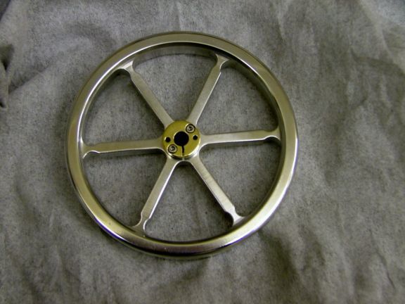
It is 7 3/4" by 3/4 thick and bored to suit a 1/2" shaft.
The boss started out at 45mm dia and is now 1 1/4" at its thickest point and 1" at its minimum.
The spokes are 6mm s/s rod from a wrecked printer, the brass is from a pipe flange and the heavy steel ring was carved out of a piece of plate.
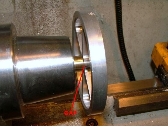
At this stage I thought, if I leave the inner dia a few thou smaller than the brass ring, I could heat shrink it on.
So after the boss, the brass ring and spokes where fitted together and checked for true, I then heated the outer steel ring and simply slipped it over the brass and quenched it to cool it down.
I also had to re-bore the 1/2" hole as the spokes where slightly proud and jutting into where the main shaft was to fit, at this stage I thought hey why don't I try to make it a taper lock, I made the angle of the compound slide on my lathe a 5 degree angle and bored the boss out then using the same setting ,I made a tapered section on a 30mm shaft and hey presto the job was done after drilling and tapping the locking screws in.
It will be finished when I have polished and painted etc.


I have been house bound for a couple of weeks now, and managed to get some quality alone time in my shed, I started out by making a steel boss for a flywheel on my lathe and it grew from there.
Sorry there is no build log or photo's, as I didn't know where this was going to go.
I slipped the boss into the div head and the flywheel just emerged from there.
It is 7 3/4" by 3/4 thick and bored to suit a 1/2" shaft.
The boss started out at 45mm dia and is now 1 1/4" at its thickest point and 1" at its minimum.
The spokes are 6mm s/s rod from a wrecked printer, the brass is from a pipe flange and the heavy steel ring was carved out of a piece of plate.
At this stage I thought, if I leave the inner dia a few thou smaller than the brass ring, I could heat shrink it on.
So after the boss, the brass ring and spokes where fitted together and checked for true, I then heated the outer steel ring and simply slipped it over the brass and quenched it to cool it down.
I also had to re-bore the 1/2" hole as the spokes where slightly proud and jutting into where the main shaft was to fit, at this stage I thought hey why don't I try to make it a taper lock, I made the angle of the compound slide on my lathe a 5 degree angle and bored the boss out then using the same setting ,I made a tapered section on a 30mm shaft and hey presto the job was done after drilling and tapping the locking screws in.
It will be finished when I have polished and painted etc.