It will not run.....

Home Model Engine Machinist Forum

Help Support Home Model Engine Machinist Forum:

This site may earn a commission from merchant affiliate links, including eBay, Amazon, and others.
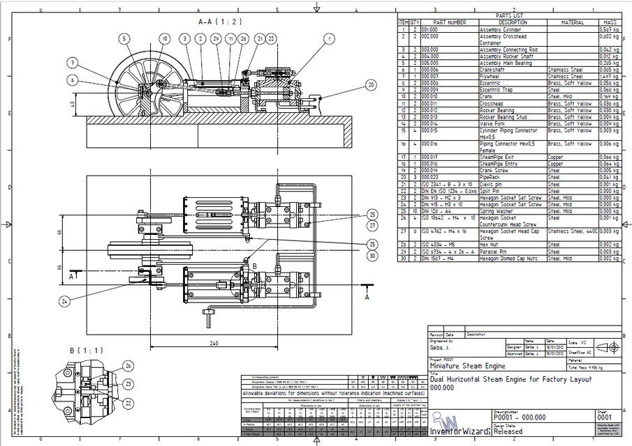
If you can get one or the other running just fine but when you pipe them together no joy. I think it is all in the valve timing. I think you need to move the eccentrics a little bit one way of the other. Looking at the one I made, I think the size of the valve and holes are ok.
What Jim said "I think your cranks need to be at 90 degrees, you have them at 180 degrees." would be better but it should run with them at 180.
 
Can anyone point me in the direction of a drw for a slide valve configuration. You are right at mid point both ports are open. Do you think the grab cad drw is in error?
 
I think I have come to same conclusion. When the slide valve is in the center position both power ports are open. I followed the drawing from grabcad to the letter could there be an error in the drawing? let me get this straight. When the slide is in the center position both power ports should be covered. I will redo the slide to a design that allows it to float up and down.
 
Be careful about what you download from Grabcad. The designs are not vetted in any manner, so unless you are experienced enough to tell when something is wrong you will be left very frustrated and confused.---Brian
 
I am finding that out now. The slide valve shaft is .240 to short as well. So I am making 2 new slide valves and 2 shafts. Again has anyone out there got a drawing or can point me in the direction of a drw that shows the relationship of slide valve to ports openings. Or do I just make sure when the slide valve is a midpoint both ports are completely covered.
 
If you keep the valve plate as it is and reduce the cavity to 7mm with no chamfer that will cure the 3 ports being uncovered. You can then either leave it with the same 14mm O/A size which gives 0.5mm lap OR reduce O/A to 13mm and have zero LAP.

If you are remaking them then I would definately go with a separate nut and slotted valve which will give better sealing

Google "slide valve lap" or "steam slide valve" and you should get the illustrations you need.

The pdf drawings are here for those that can't see decent sized drawings?
https://grabcad.com/library/dual-ho...in-factory-layout-1/details?folder_id=1536875
 
Here are the drawings
upload_2018-8-4_8-29-0.jpeg


upload_2018-8-4_8-29-44.jpeg


upload_2018-8-4_8-30-14.jpeg
 
JM
"When the slide valve is in the center position both power ports are open. I followed the drawing from grabcad to the letter could there be an error in the drawing? let me get this straight. When the slide is in the center position both power ports should be covered. I will redo the slide to a design that allows it to float up and down."

This is NOT True when the slide valve is in the center position the EXHAUST port is open to both ends of the cylinder. The air should be going in to the steam chest.
 
The problem is that as the valve starts to uncover the inlet port it is not wide enough to close off the exhaust port so instead of the air flowing from valve chest through the inlet port to the cylinder (blue line) it will take the easiest route and go straight out the exhaust (red line)

The flywheel probably carries the engine over when run as a single with just some wasted air but if the timing is not right or there is tightness when the two are run together the engine will stall and just blow the air to waste.

Combine this loss of air and the 0.5mm lap and the piston won't be getting the full incomming air until 54deg past dead ctr so a lot of the power stroke is lost

I have done a quick sketch to the printed drawing, the OP has used wider 1/8" slots going by pencil notes so problem will be a bit worse.
 

Attachments

  • factory valve.JPG
    factory valve.JPG
    31.1 KB · Views: 206
Last edited:
The problem is that as the valve starts to uncover the inlet port it is not wide enough to close off the exhaust port so instead of the air flowing from valve chest through the inlet port to the cylinder (blue line) it will take the easiest route and go straight out the exhaust (red line)

The flywheel probably carries the engine over when run as a single with just some wasted air but if the timing is not right or there is tightness when the two are run together the engine will stall and just blow the air to waste.

Combine this loss of air and the 0.5mm lap and the piston won't be getting the full incomming air until 54deg past dead ctr so a lot of the power stroke is lost

I have done a quick sketch to the printed drawing, the OP has used wider 1/8" slots going by pencil notes so problem will be a bit worse.
 
Thank you guys for all your help. I am still a bit unclear. See the sketch below I got on line

upload_2018-8-5_9-43-26.png

Both power ports are covered when the slide valve is in the center and the exhaust is open. As the valve moves to allow steam in the other port is open to exhaust. I am just trying to find the right dimensions to machine the new slide valve
 
I think the dimensions on the drawing are askew , the recess would work better if it was 7mm maximum with no chamfer .
The ports are on 5mm centres so the dimension for the outer ports centres is 10mm from that subtract the width of one port (3mm ) and this will give you dimension of the inside edge of the outer ports (7mm) . If you follow the plans the recess is 8mm long and has a 0.5mm chamfer all around so the actual size of the recess is 9mm . This means that not only is the exhaust open to both ports at the same time it is also getting blow by from the steam chest , ideally you want one port just open , one just shut and that goes for the intake and exhaust events . If you have used a different size cutter to mill the ports i would take a set of dial or digital callipers and measure from one inside edge of the outer port to the other inside edge of the other outer port and make the recess to that dimension or a little smaller , 0.5 mm or so . You will need to measure the outer edges of the same ports to ensure the valve is long enough as well .
I think your sketch is really only to show the general arrangement , you should be able to find something on youtube to show how the valve timing events . Also have a look at Keith appleton on youtube , he did make a video of setting the timing correctly .
 
Based on your penciled in dimensions this valve should work. I have shown a loose nut so valve will seat better and be able to lift if needed. Very little lap as it is not needed for running on air.

Two Jpgs showing valve at mid point and max eccentric throw plus a pdf drawing.
factory rev valve1.JPG
factory rev valve2.JPG
 

Attachments

  • factory revised valve and nut.pdf
    32.7 KB · Views: 207
Jasonb
I am going out and stating to build this right now. I will send you progress pics. Thanks for the help
 
Interesting this drawing shows the cranks90 out and not hitting TDC at the same time.
large.png
 
Cranks on that drawing are at 180 degrees, look at the balance weights

180deg.JPG
 
Last edited:
My mistake. I doubt the author creator had much interest or experience in steam.
I doubt a full size engine would start unless in the right part of the cycle. If stopped at top or bottom the engine will not start.
The biggest engines had barring engines to move the engine off center
 
Jmccrmc, the diagram you found, I-I is less than D-D. That is called 'exhaust lap'. The design you are working from had I-I greater than D-D, which is called 'exhaust clearance'. As a rule, in model work (and mostly in full-size too) neither of these is a good idea: In the great majority of cases I-I is made equal to D-D, in which case the exhaust is said to be 'line on line'. Nobody who knows anything would design a chamfer on any of the edges, and nor would they design a slide valve that has no means of movement perpendicular to the port face.

The cages over the crossheads are also an aberration that I have never seen anything the like of in hundreds of full size engines seen live, in drawings or in photographs. I am not saying such a thing does not exist, just that if it does, it is mighty rare. Though, of course ones imagination need not be constrained by past practice.
 
Back
Top