IH Mill Prep for CNC Conversion: One shot oiler, Z-mod, etc.

Home Model Engine Machinist Forum

Help Support Home Model Engine Machinist Forum:

This site may earn a commission from merchant affiliate links, including eBay, Amazon, and others.

BobWarfield

Well-Known Member
Joined
Dec 27, 2007
Messages
1,151
Reaction score
1
I'm getting ready to start the CNC conversion on my IH mill, so there's tons of prep work for me to do. I started out lapping the ways as recommended by IH. It's a controversial subject, but after trying the "before" and "after" I'm satisfied it's a good thing. The purposes is to get rid of some of the worst friction from tool marks without going too far and affecting the trueness of the surfaces. Done right, it lets you run the gibs tighter and get smoother way action. I certainly was able to feel a profound difference.

You can read more detail on my site:

http://www.cnccookbook.com/CCMillCNCHome.html

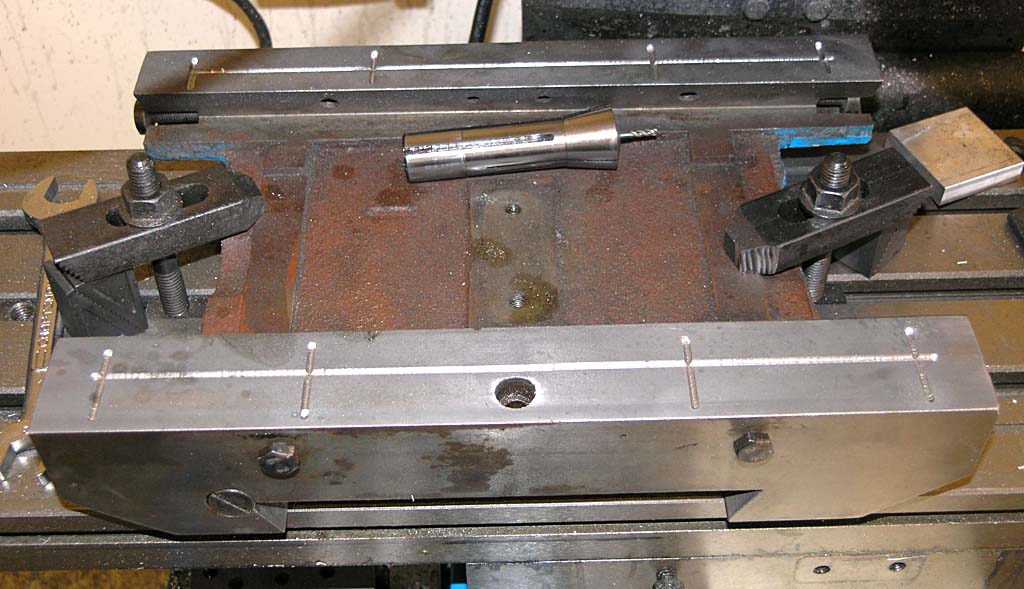
Next up is a mod to the Z-axis that is beneficial for RF-45 mills. The bracket that connects the Z-carriage to the leadscrew nut is just a loose fitting bushing. This can lead to quite a bit of slop in the head. Normally this wouldn't matter as I think the designers intend for precision Z-work to be done with the quill rather than by raising or lowering the head. But for CNC, it matters a lot as the quill is not used. So, you have to cut a shoulder in the head and fabricate a steel bushing to match so that you can clamp the bracket to the head. Here is the new bushing next to the old one:

P1010272.JPG


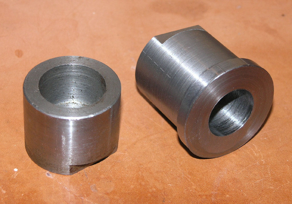
The shoulder lets you torque down the bolt and lock the nut bracket to the slide.

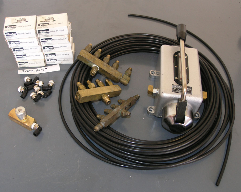
Next, I got started modifying my Z-axis for a one shot oiling system. I figure while I have the mill apart, I'm going to do it up right! I had bought a one shot lever-type Bijur oil pump off eBay for cheap. There's a page on my site with details of how others have added one shot oiling:

http://www.cnccookbook.com/CCMilllOneShot.htm

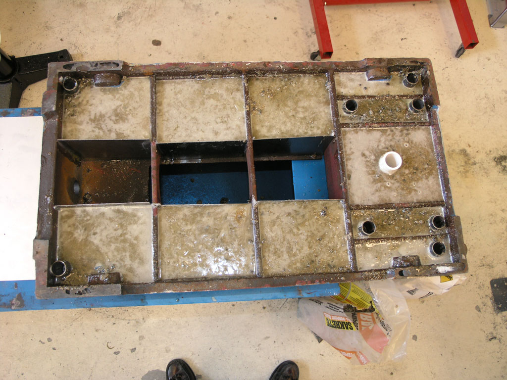
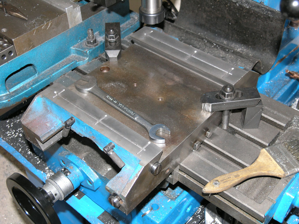
Now it's my turn. I started out cutting some oil distribution grooves in the Z-saddle ways that match up to the original oil ports:

P1010273.JPG


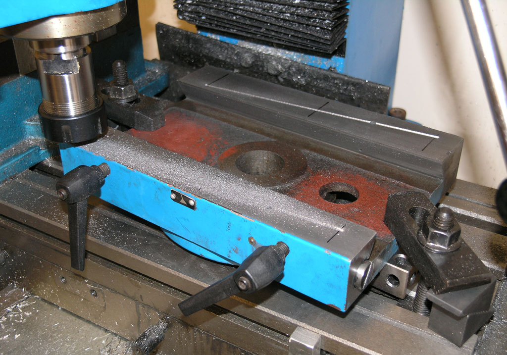
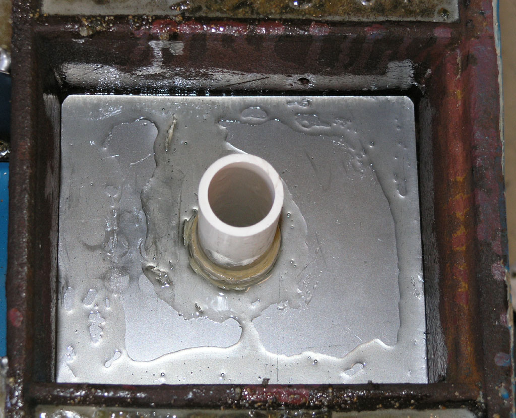
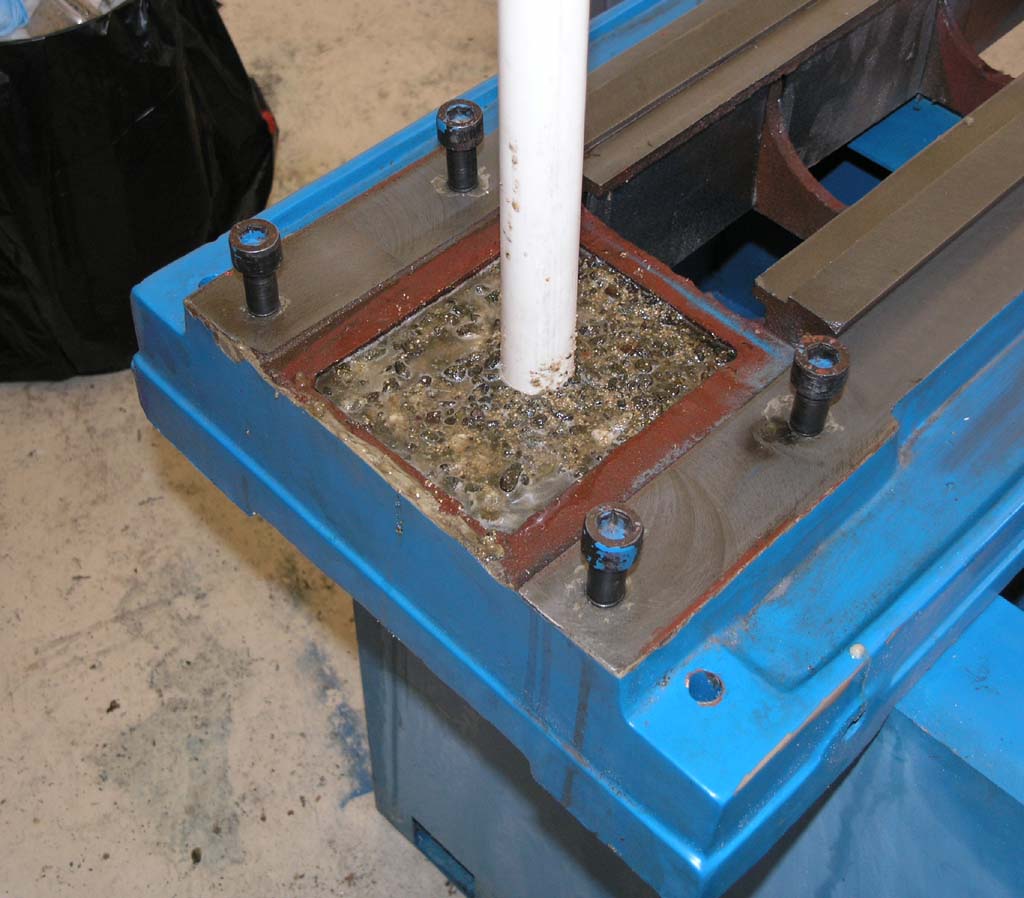
When I got done I set the Z-saddle on the column and injected oil through the original ball ports to try it out. It works really well, big improvement in the oiling!

P1010275.JPG


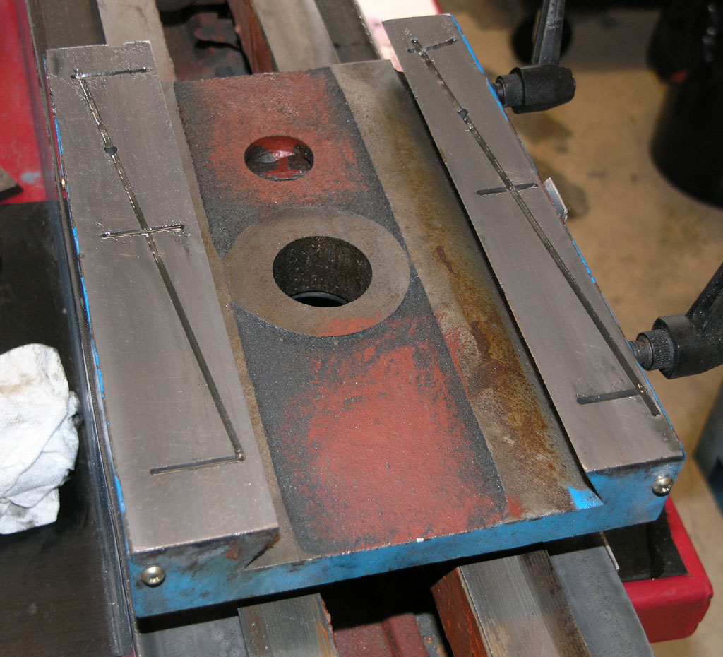
I was able to get just the right amount of oil evenly spread with this grooving system. I'll call that a lucky break. The grooves were cut with a 1/8" ball mill.

For those of you wondering, I own 2 of these IH mills, so I'm modifying one by using the other.

I'm not nearly done with the one shot oiler, so this will be a work in progress thread.

Best,

BW


For those of you wondering, I own 2 of these IH mills, so I'm modifying one by using the other.

Best,

BW
[/quote]
I was wondering about that, if you were going to end up with just a cnc mill..I have both manual and cnc mills and would hate to be in position to have to choose to keep just manual or just cncs......Uhmmmm, I upgraded an old 1980 ,3500 pound Hurco cnc mill, runs off PC with Mach3, good machine for lot'sa work but I am left wanting small tabletop cnc mill for engraving and such small work ...Particularly because the spindle on my cnc bedmill tops out at 3500rpms, and need/want much faster spindle for using very small carbide endmills.....'Nuther words there opportunity for small cnc mill to have significant advantages over the larger sized industrial duty CNC vert mills......
 
Alpha, there are various things you can do about the spindle issue. The simplest is to mount an auxilliary high speed spindle (a Proxxon/Dremel type tool or a laminate router) alongside the main spindle. Perhaps the most complex is to reengineer the main spindle for higher speeds. You won't hit the speeds of the Proxon/Router solution, but I don't see any reason you couldn't get 8K-10K rpm which would be a lot nicer for aluminum. It's on my list to work on that after I get my mill converted.

In terms of having only CNC and no manual machines, I don't personally have a problem with that. I could live with CNC alone very happily, but I can see where others might be less comfortable. Part of it will have to do with the conversational interface to your controller (if any) and the availability of good CAM software that you're comfortable with. If you've got to write all the gcode by hand and the conversational is limited, I could see that being a problem.

Best,

BW
 
I could do fine with just a cnc mill but fortunately I dont have to make that choice..I have 2 cnc mills weighs 3500 lbs and thuther weighs 5000 lbs but I plenty of room for'em..Plus I have 2 fullsized manual Bridgeport clone knee mills....Yes I could put a high speed spindle motor attachment to one of them, indeed I have one for that purpose, but there is another problem- for engraving where there needs to be a go-zillion rapid moves of the table and the Z , I rather put that wear and tear on a little tabletop machine made specifically for that small work.......Y'cant get too many machines,....Yeup I want a lil tabletop cnc mill, lil lathe done up as cnc for making bolts would be mighty fine too...Saturday I am picking up a monster old TIG welder, nasty old POS but I pretty excited about it, new toys for the shop is always cause for celebration..Love old iron.
 
Here are the various eBay goodies I've accumulated for the one shot oiling system:

P1010283.JPG


I reckon that's just about $100 worth of stuff there. The key components are Legris push-in fittings and a set of flow control valves I found cheap:

P1010280.JPG


The flow control valves let me individually tune each of the 9 circuits (one for each way side plus ball screw nut for each of 3 axes), and also incorporates a check valve so oil flow is always towards the ways.

I got grooves on another axis but then had to stop to help my brother make a new part for his Audi TT. Here's the saddle with one axis done:

P1010277.JPG


More to come. I'm also planning an epoxy granite fill for the base and column.

Best,

BW
 
Got my last set of ways grooved this morning:

P1010293.JPG


That's the x-axis. Along the way, I managed to break 3 end mills to do all 3 ways. I decided that wasn't right and checked out my ER32 collet chuck. Sure enough, the darned thing had noticeable runout. It's a real cheapie from 800 watt. I can't tell if it's the chuck or the collet, but it doesn't take much before 1/8" end mills break! So, I ordered 2 new Bison Er32's today. I will see how they like the cheap collets. If I still have much runout, I'll probably invest in a Bison set. Incidentally, I regreted the purchase. Bison makes nice stuff, but Maritool has ER32 chucks for just $50 odd--that's a real steal. The guys on the PM board love Mari, so if you're in the market for an ER chuck, I'd check Mari first.

In the meanwhile, I did the whole X-axis with a single end mill in an R8 collet--no breakage.

I still have a lot of work to do to finish the oiling system. I've got to drill intersecting passages, tap for fittings, mount various brackets to hold it all, figure out how I'm getting oil to leadscrew nuts, yada, yada. I'll keep you posted on all that in this thread.

Meanwhile, I am also planning to fill the base of the machine, and perhaps part of the column with Epoxy Granite to increase dynamic stiffness. I got this idea over on CNCZone, but big time outfits like Hardinge do it too. It's pretty darned easy way to add mass and rigidity to your machine, so I figured I'd try it. The word is that Epoxy Granite is about 8x better at vibration dampening than cast iron. My hope is that this will translate to better surface finish and perhaps an ability to take a bigger cut.

First step on that is to fab a containment system for the epoxy:

P1010290.JPG


There's a lot more detail about this on my web page: http://www.cnccookbook.com/CCMillEpoxyFill.htm

In particular, you can see pix of another fellow's similar effort that he has finished.

Best,

BW
 
I'm excited to see how this turns out
afro.gif


Thanks for sharing, Wes
 
Im am wanting to follow this thread too.

I like what Evan at HSM had done with his home made cnc. I have been looking at the plasmacam system and the carvewright CNC router machines too.


Im a computer nerd, a cnc would be so nice to have and if it is home made then there will be less mystery when it goes haywire.

keep up the good work.


The Epoxy Granite experiment has progressed to the mud pie making stage!

I did a bunch of tests mixing sand and gravel and checking the epoxy required with water as a substitute. Based on the experiences from the big CNCZone E/G thread, I was shooting to find a ratio that had me at a little under 15% Epoxy by weight, and 85% the rest of the aggregate. The real pros can get this down to more like 7% epoxy, but I'm not trying to over optimize the problem. Once I had my proportions figured out (full details on that on my web page: http://www.cnccookbook.com/CCMillEpoxyFill.htm ), it was time to do a trial batch and see how it came out. FWIW, The mixture I arrived at with the water tests wound up using these proportions by weight with epoxy resin:


62% gravel

23% sand

14% epoxy resin


That worked out pretty darned well if I do say so myself. In terms of volumes, this was 1/8+1/4+1/3 cup of gravel, 1/4 cup of sand, and 1 1/2 pumps each of resin and hardener. I wouldn't over analyze any of these numbers, BTW. Here's what you need to mix up this stuff:

P1010298.JPG


The pumps are real nice. They meter out the right proportions of resin and hardener, and the instructions say just leave 'em on the cans when you put them into storage and they'll be fine. Keep in mind, epoxy builds up a stronger and stronger allergic reaction from exposure, so you don't want to get any on your skin! I wore rubber gloves and eye protection and was really really careful with the stuff.

So, after all that, here is what an Epoxy Granite "Mud Pie" test looks like:

P1010300.JPG


Tomorrow I'll see how it has set up. If it looks good, I'll start doing the pour on the machine base using these proportions. If this turns out to be a useful way to improve a machine, it has to be one of the easiest mods I've done in a long time!

I'll keep ya'll posted...

BW

 
Heya Bob. I am real curious to see how this works out for ya. I had been following the CNCzone thread on EG as well... I noticed you had posted on that thread. What prompted you to go with this mix?

Eric

 
If you're wondering why I'm doing this crazy thing--it seems a cheap and easy way to add dynamic stiffness to a machine. Companies like Hardinge do something real similar and it works great. Drag racers have been filling the bottom part of the water jacket on their engine blocks with something like this for a long time and that works great too. If it works for me, my surface finish improves and I can take deeper cuts without chatter. It's all about mass. Look how much even a small commercial CNC weighs (about 3,000 lbs or more) versus even a big bench mill like my Industrial Hobbies (not quite 1000lbs). We need to add mass. I've also heard of fellas concrete filling the column on a round column mill and liking the results, FWIW.

If you're wondering how I came to the exact composition of the mix, it boils down like this: I read through the entire E/G thread on CNC zone, which is ridiculously long. The basic conclusion or principles they're working from boil down to a desire to minimize the epoxy by using various sizes of aggregate components that work together to minimize the voids between the particles.

If they do everything EXACTLY right, the professionals can get down to maybe 7% epoxy by weight and 93% aggregate. But, there are all sorts of issues getting there. OTOH, everyone agrees its really easy to mix up something and get to 20% epoxy and that is workable. And, there seems to be a consensus that anything in the 15% and under range is getting to be "pro" quality. So that 15% became my "good enough for me" target.

Why the fixation on minimizing the epoxy? Two reasons. First, epoxy resin is expensive. Second, the granite is where all the strength is. The role of the epoxy is simply to hold it together to form a composite material.

Rather than deal with all the complex math the CNCZone guys were doing, and rather than order special aggregates in 5 different sizes, I wanted an easier way. So I bought some granite gravel and some play sand at home depot, and started doing mixture ratio experiments. I just wanted to find a proportion that got me to 15% epoxy or less by weight. I used water as a substitute, and just measured how much water "fit" after I mixed an aggregate sample. Didn't take long to figure out a formula by experimentation. In this practice trial, I hit the nail on the head in terms of my epoxy goal of under 15% by getting to 14%.

There are also consistency rules of thumb: make a snowball out of your epoxy granite mix. If it collapses into clumps, add resin. If it runs through your fingers, add aggregate. If it holds together as a snowball, you've got a good mixture. My trial passed that test too.

Now I have to see how it looks after setting up. If it's good, I'm ready to start pouring the stuff into the machine base.

I want to do the column too, but that'll be touchier in order to leave enough room for the leadscrew. We will see.

Cheers!

BW
 
What sort of mass gain are expecting from filling the base?

Eric
 
The fella that gave me the idea for this said his base started at about 100lb and was 180lb when he finished. I think that base is smaller on the basic RF-45 mill than the IH mill. At least the RF-45 has less webbing in it, so I may be a little bit heavier. You can see from the pictures that there's a lot of air space that will be filled with a material whose density will be pretty close to granite's.

I won't be able to fill as great a proportion of the column, and that's all still to be worked out.

I'm glad I built my mill table so strong!

Best,

BW
 
I went down to check the test batch this morning and was very pleased:

P1010301.JPG


P1010302.JPG


Some observations:

- The material set up very nicely. The only air bubbles were at the top. The epoxy is clear and I didn't see any embedded with the aggregate. Could be dumb luck, but the West Epoxy seems to wet really well. Vibrating Tables and Vacuum Chambers were not needed here.

- It faithfully reproduces the mold in minute detail. You can see tiny scratches that were in the plastic cup from the sharp gravel edges reproduced in the epoxy. If you have a precision mold, you will get a precision surface back on the epoxy. Imagine making a lathe or mill headstock out of this stuff. Your precision surface is the machined outside cylinder of a cartridge spindle. Just mold it in place and you have a solid epoxy granite headstock that should be pretty darned solid for machine work.

- The finish is very nice where it was in contact with the mold. It looks polished and is definitely clear enough to see inside. I don't know that I'd try to make a window out of it, but it's a nice finish from an aesthetic standpoint. Looking at pix of some finished E/G machines, I'd always wondered how hard it is to get a nice finish. Came for free on this experiment!

I won't have time today to do the base pour, so I'll probably tackle that in the morning.

Runner440 from CNCZone has PM'd me with an important suggestion for others who may be following the same path. To install the IH CNC kit sometimes requires a little grinding on the underside of the casting to clear the ballnut. I understand perhaps 1/8" of material may need to be removed. Once the E/G dams and/or pour are done, you won't have clearance to get an angle grinder in there. You want to make sure you have either done the grinding beforehand, or that you have a way to get in there to do the job with limited clearance.

In my case I will use a long-nosed grinder I have for head porting, or I will put the base up on my other IH mill and mill a little pocket. I can definitely get in there with my 2" face mill to do that if need be.

Another good suggestion I got was to extend the dams so that the base picks up an inch or so of E/G on the bottom. This allows for the addition of considerably more E/G mass, as well as providing an opportunity to tie across the leadscrew cavity more strongly. I'm very tempted to do this, and undecided, but I probably won't go there. It would mean a lot of extra work and delay, and I'm anxious to keep going on this one.

So far, the E/G process has been fun and easy. That probably means a painful screwup is right around the corner. I'll let you know what it is so you can avoid it!

This is a material that I think has application to our hobby. It has the potential to substitute for cast iron to create mass, or even as a casting ala the lathe headstock idea. It also has aethetic promise for those looking after unique "bling". The knife making crowd are into what they call "Micarta" as a material for knife handles. This is just material embedded in resin. They want something more attractive than pebbles and sand, but the results they achieve are quite interesting:

Jeansimg1550s6vb1.jpg


That's made from blue jeans material embedded in resin. I'm imagining one of you guys' gorgeous model engines sitting on a base made from some cool Micarta. How about one of those dual test tube engines on a base of Micarta with embedded carbon fiber cloth? There's some cool possibilities there if you like to tinker!

Cheers,

BW
 
I have made progress on filling my mill base with Epoxy Granite. All the bays except the big hole under the column have been filled:

P1010343.JPG


The two little center bays on the bottom are still wet. I agonized over them. They house the column mounting bolts, which I did not want to foul up with any leaking epoxy. I had some small leaks on 2 of the centering holes. It seems it's very hard to get a perfect seal between the silicone and the casting/pipe even if you use a large fillet and drop straight down with no side to side motion.

The leaks I got were just a few drops, but a few drops of epoxy would foul up the threads on those holes terribly. It would be the end of the world, but drilling them out and tapping would be a painful nuisance.

I decided to insert the bolts just a little to seal the bottom of the hole, and then pour molten candle wax in on top. I used a torch and candle to supply the wax and poured until the was was above the casting/pipe seam.

P1010340.JPG


I'll have to wait until the epoxy dries before I can melt out the wax and see that the hole threads are good to know for sure. Early indications are that it certainly looks good. You can see on the picture at the top of the post the wax (disturbingly the same color as the epoxy, but that is wax!) is fairly pristine. There's a little sand in one hole from when I went along at the end and added some sand to soak up excess epoxy.

Keep fingers crossed for me!

Cheers,

BW

PS Next step is to engineer a big connecting bolt with the column, and then from there to start filling the column. I also need to finish the one shot oiler work. Never enough time in the shop!
 
FWIW, I used to make indoor rock climbing holds from resin and sand (commercially they mostly use glass beads nowdays)-- big ones would get hot enough to melt wax when they set up, so that might not be good as a hole-maintaining material. It's amazing how well the texture and surface of the mold is preserved,even though the material is mostly sand, none of it ends up on the surface-- I used various types of foam to get the texture I wanted. I did notice that dimensions would occasionally change when not confined, so you might not want to rely on it for precision surfaces.

I disagree that the epoxy doesn't provide any strength though-- it's pretty tough stuff all on it's own, and I always felt the sand was in parge part just taking up space the more expensive resin would otherwise need to occupy.


Shred, I too have worked with epoxy and had it "heat kick" and get really hot. This stuff has not done done that as yet. Barely warm to the touch. I think we're okay as far as not melting the wax, but I'll no more tomorrow.

I wouldn't say the epoxy contributes no strength, but the sand and granite are more than just "epoxy displacers". If nothing else, the increase in density they provide makes the material a better vibration dampner.

This stuff does mold very very well too. I'm anxious to come up with a project using it that involves a precision mold.

Cheers,

BW
 
Yeah, for this purpose, the additional weight and dampening is good. Rock gyms don't like weight though.. ;)

I did see some annoying dimensional changes every so often, so you'd want to check precision surfaces, but most of mine were in latex molds in a sand bed, so we weren't trying for much dimensional consistency to begin with.


At last the base is filled. I had to wait for my brother's day off for him to come over and help me flip the base for a final pour on top. It now weighs close to 200lbs and is noticeably "deader". A couple pix:

P1010376.JPG


That steel plate fills the old open hole and locates a new center hole for a 1 1/8" bolt to add column to base rigidity.

P1010379.JPG


Bottom-side fills are done. Flipped it and poured the top:

P1010388.JPG


While the top was drying I set out to make a set of leveling feet from hockey pucks for this mill:

P1010389.JPG


I have some minor trimming on the base to do, but I'm about ready to start planning the column fill next. BTW, filling the column bolt holes with wax worked perfectly. Whew!

Best,

BW
 

Latest posts

Back
Top