Ignore this topic

Home Model Engine Machinist Forum

Help Support Home Model Engine Machinist Forum:

This site may earn a commission from merchant affiliate links, including eBay, Amazon, and others.
Status
Not open for further replies.
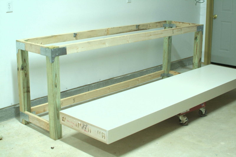
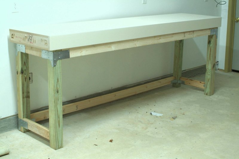
I put together a new workbench for one side of the garage nearest the mill. The frame is held together with Simpson metal ties and about 100 screws. I have built a workbench and some shelving before with these brackets, and they work well.

The top is 9' x 26" by 5". I got it from a cabinet maker locally who had built it for a bankrupt homebuilder. The front, back, and sides are maple, with the top and bottom being 1" thick MDF. I'd estimate it weighs about 120 pounds. My other workbench has a butcherblock top with the vise and arbor press bolted to it. This one will be used for lighter duty work.

I followed Marv's specification as to the height, which is 42", for comfort when standing. I will add a half-depth shelf underneath for extra storage. Total cost was about $130.

large.jpg


large.jpg
 
So I got a disk from Aussieland ;D AND it doesn't work :-[

TurboCad is not to be. Jack if you read this: The disc looks like someone spit on it and wiped it with their shirt before putting it in the mailer... :mad: The computer simply does not recognize that a disc is even present in the drive.


SO I never unloaded TigerCAD and have been playing with it for several weeks now. and I'm really starting to like it. maybe its because I've never used a CAD program before. ???

Just some things my brain made me type,
Kermit ;)

Edit: I'm adding the latest experimental stage of my drawings for the vertical Osc build. This was done with CutePDF(another free program), and it's in Arch D scale so Zoom in on it for detail. :D


View attachment Vert Osc 1 Cyl_REVB.pdf
 
We need to be careful with our shop dogs.
Some breeds are listed as being dangerous.
Our new boxer is a breed on that list along with rottweilers
and the MOST dangerous the pit bull terrior.

Small children should NEVER be left alone with these dogs.
One irresponsible dog owner did exactly that!
The results were horrific!

Please don't allow this to happen to YOUR home or shop!

DangerousDogBreedPhoto.jpg


;)
Rick
 
Get??? Make you mean - they are a pleasant little exercise and you can make what you want, not what some factory thinks you want.

I'm with Tel, I bought an R8 shank slitting saw arbor that had spring loaded center sleeves to take varying saw hole sizes. The two issues I had were that with the small saws (2 1/2 dia) the holder reduces the possible depth of cut too much and the sleeves are not the correct size for imperial saws (OK for metric). That means the saw wont sit on center and gives an interrupted cut.

I'll be making some dedicated straight shank arbors for the 3 blades I have.

Cheers
Phil
 
Ok I have the cam completed. I had to change it up a bit so that I had a short 1/2" shaft to one side so I could press it into the gear I had made several years ago when I was playing around making gears.
Here is the gear:
IMG00174-20090419-1825.jpg

Here is the cam on the mill:
IMG00008-20090424-1026.jpg

I have the gear and the cam on my arbor press and will press the cam into the gear:
IMG00013-20090424-1104.jpg

Now pressing the bearing into the cam (both sides)
IMG00019-20090424-1108.jpg


That's it for now. I thought I had taken a pic of the bearings pressed into the cam but I guess not. I will take one and update later.

Next is to finish up the flat plate work.
 
I finished all the machining of parts and assembled the engine. Now I need to get it running.

Charlie

DSCF0050.JPG


DSCF0051.JPG


DSCF0052.JPG
 
Hi Guys
I'm trying to post my first vid. It's an Mpeg, but photobucket won't take it. Where do I go and or what do I do???? Create a URL some place else for vids??
Tony


Never mind, I think I've got it. PBuckets help is pretty good!
 
All you have to do to get rid of the heat is turn the reflector so the sun isn't hitting it and the heat source (most of it anyway...) is no longer a problem. Have you ever cooked over a campfire or used a propane torch? same kind of danger, just took a bit longer getting fro solar to heat...

Starting to sound like those paranoid safety freaks that take everything away that might injure someone. (or maybe a lawyer) Have us all living in rubber rooms and then wonder why we all die from stress.
 
Geez George...been working on my boat and just saw this!


Damn!!

Beautiful!!!!!


Dave
 
Don't get too stressed out about those finishes. YOu can get a GOOD SMOOTH finish by polishing with some 400 grit emery paper. You are looking for a SMOOTH surface that will not wear out the bearing and that can have a nice film of oil cling to it.

It just wants to be smooth and shiny.
 
One that I have used is PDF Creator. Will at least print to 8.5 x 11 and 11 x 17. Installs as a printer and lets you change the file name.

http://www.pdfforge.org/
 
All I have ever used is center drills...
 
Here's the info off the Aussie_9x20_owners yahoo group. (used with permission)

The Group meets on the third Sunday each month (this month Sunday 21st JUNE,
2009) - at:

McDonalds McCafe
Corner Canning Highway and Berwick Street
Victoria Park
Western Australia

at about 7.00 pm

Turning, milling, welding, CNC, EDM, laser cutting, casting, electroplating,
anodising, group projects, bring show-and-tell, suggest group projects, etc

BYO (buy your own) coffee & cakes.

Phone me on 0412 768 348 if you need more info

All welcome
Jack


Hope to see some of you Perth guys there, I'll bring my QCTP project.
Cheers
Phil
 
The one shop I worked in that machined Magnesium had a bucket hung on a post next to the machine with a compound they called Purple K. Was only for magnesium fires.
 
Crap crap and crap. Beet! That is just so wrong and disappointing.
Oh please Mr Moderator correct that or tell me how.
Bummer.

Glad you enjoyed it. It was a lot of fun.

Ah the words of the great bard come to mind...

"Methinks you protest too much."

[EDIT: Well I did mention the experiments. How can anyone expect me to type under these conditions?]
 
I decided it was time to move the air conditioner to a wall. I had one wall yet that didn't have wall covering on it, just house wrap on the one side and plastic on the other with insulating in between. I used metal studs for the interior walls and I never did care for them. I decided to buy a couple of 2x4x10 studs and replace the metal studs with these where the air conditioner was to go. Well one thing led to another and the next thing I knew I had all the house wrap remove, plastic, and the insulation pulled out and I replaced all the metal studs. Next I went and bought paint and wall covering and I am now putting on the last coat of paint. I have more staining left to do on the cabin so I will get up very early tomorrow and have the last coat of paint on the walls before I have to start staining again.

Here are some shots of the shop in transition. Once I get all the paint on and things back where they belong I will take the finished pictures.


IMG00136-20090704-1722.jpg


IMG00135-20090704-1603.jpg


IMG00140-20090704-2126.jpg


Well the wall is finished, all walls have 2 coats of paint and I have run a pipe through the wall for shop air::))

Here it is ready for the electrical.
IMG00138-20090704-2125.jpg


This is what it looks like now. I moved the lathe which is to the left of the desk back against the wall and it opened the room up just a bit. I also swapped the desk with the work bench so I wasn't backing my chair into the grinder handle.
IMG00142-20090718-1804.jpg


This wall was only partially painted before and there was no trim around the doors. I still need to paint the trim.....someday..:)
IMG00143-20090718-1804.jpg


I really like having the white board behind the mill like this. It comes in very handy when making notes of dimensions or sketching a part out.
IMG00144-20090718-1805.jpg


I found a metal bracket in the other part of the shop and hung my tool post holder on it. I also moved the collect rack. I think I am going to like this set up much better.
IMG00145-20090718-1806.jpg
 
Here's my parting tool holder,
It seems that I have the ability to complicate a simple design so that it blows out to a big job. :toilet:
I should have stuck to your design Gail. :wall:

The design is similar to one I saw in a catalogue but is incorporated into the holder and not just held by it.

P1070125.jpg

Just got to find a couple of more M4 cap screws.


I started by cutting a shallow dovetail near the bottom of the holder. The parting off blade is 2.5mm thick so I made the dovetail 2.6mm deep.
The parting blade has a V shape both top and bottom.

P1070080.jpg


The next operation was to remove the excess material from the holder. 12.5mm deep and to below the height of the parting blade.

P1070081.jpg


P1070082.jpg


From there I set the holder up at 45° in a V block to mill a sloped register that will pull the blade hard into the holder.

P1070084.jpg


P1070083.jpg


P1070085.jpg


With the holder done, It was time to cut some flat bar for the blade top cap.

P1070087.jpg

That was as far as I got before I needed a cup of tea.

When I finally got through that, I squared and cut the stock to length.
There is a small piece of flat bar at the other end of the vice jaws to keep the vice jaws square.

P1070089.jpg


I then cut another 60° dovetail 2.6mm deep (sorry no pic) but you can see it is this set-up.

With the dovetail cut, I set the cap at 45° and milled the mating register.

P1070091.jpg


P1070093.jpg


Again the excess metal was cut milled away.

P1070095.jpg


That's where the progress pictures stop. The camera was in use for baby snaps.

To complete the job,
I needed to trim the horizontal top surface of the holder so that the 45° register pulled the blade in just before the top cap bedded down on that horizontal surface. I also had to adjust the dovetail that clamps the blade down so that it clamped the blade just before the cap beds down as well.
So are the issues of making the holder before putting pen to paper. ;D

P1070127.jpg


Then I drilled and tapped four M4 holes that seat in the middle line of the top cap.
The cap clamps on the blade and the register while leaving a small clearance on the horizontal surface.

A quick test run confirmed the all works well. When I get my but into gear, I'll post a drawing.

Cheers
Phil


Status
Not open for further replies.

Latest posts

Back
Top