Looking for a good source for coils for your model engines? Here is what I have recently started using. They are cheap, easy to make and extremely plentiful. Millions are just waiting for you in your local junkyards.
They are the COP ignition systems used on all modern cars since the late 1980s. COP stands for Coil-Over-Plug, where each plug has its own coil. They are small, easy to modify for your models and powerful enough to meet most needs.
I bought a set of eight COPs for a 1980's Ford van from a local junkyard for $40 USD. That translates to a mere $5 per coil. If you dont need eight then get a set from a 6 or 4 cylinder engine. I suspect yards that allow you to pull your own parts will sell you one at a time.
The first picture shows a COP just as it came from the yard. The second picture shows it with the boot removed. Remove the boot simply by grabbing and pulling it firmly. Sometimes it may take a slight twist.
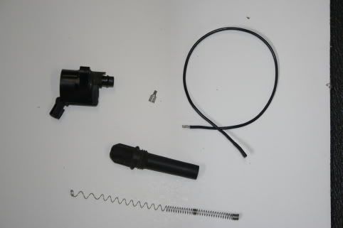
The next step is to remove the spring. More rocket science, grab and pull, it will stretch out a bit but should pull off easily. You are now in possession of a basic ignition coil. If you look into the hole where the spring was you will see a flat spade type of connector. This is where you will connect the wire to the spark plug. Look close at the picture and you will see the female connector I used to attach to the wire and which slides over the spade connector. I don't know what they are called but I got mine from one of those electrical connector packs you can get at most hardware stores.
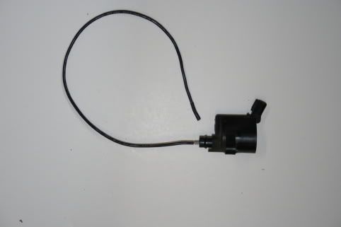
The next picture is the finished coil ready to install. Total time, about ten minutes. Not shown is the wires that come from the electrical source. On the COPs I got the wires were missing so I have to make them. Not a big deal, just a bit if a pain. Be sure when you get yours that you get them with the lead in wires attached. Save some time.
I have experimented with this coil some and found it works with any engine I have and does the job whether 6V, 12V or 9V. I ran an engine at last years GEARS show using 9V batteries. Think I went thru two. It also worked with the low-tension circuit using an Ignitor.
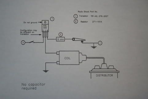
The last picture is the schematic for the transistor circuit I use on all my engines. I do not know who made this design as I was given this many years ago. Works great. If anyone is interested in this circuit I will be willing to cover it in a separate post.
Hope this helps.
They are the COP ignition systems used on all modern cars since the late 1980s. COP stands for Coil-Over-Plug, where each plug has its own coil. They are small, easy to modify for your models and powerful enough to meet most needs.
I bought a set of eight COPs for a 1980's Ford van from a local junkyard for $40 USD. That translates to a mere $5 per coil. If you dont need eight then get a set from a 6 or 4 cylinder engine. I suspect yards that allow you to pull your own parts will sell you one at a time.
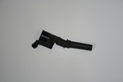
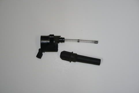
The first picture shows a COP just as it came from the yard. The second picture shows it with the boot removed. Remove the boot simply by grabbing and pulling it firmly. Sometimes it may take a slight twist.
The next step is to remove the spring. More rocket science, grab and pull, it will stretch out a bit but should pull off easily. You are now in possession of a basic ignition coil. If you look into the hole where the spring was you will see a flat spade type of connector. This is where you will connect the wire to the spark plug. Look close at the picture and you will see the female connector I used to attach to the wire and which slides over the spade connector. I don't know what they are called but I got mine from one of those electrical connector packs you can get at most hardware stores.
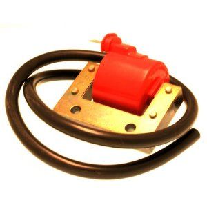
The next picture is the finished coil ready to install. Total time, about ten minutes. Not shown is the wires that come from the electrical source. On the COPs I got the wires were missing so I have to make them. Not a big deal, just a bit if a pain. Be sure when you get yours that you get them with the lead in wires attached. Save some time.
I have experimented with this coil some and found it works with any engine I have and does the job whether 6V, 12V or 9V. I ran an engine at last years GEARS show using 9V batteries. Think I went thru two. It also worked with the low-tension circuit using an Ignitor.
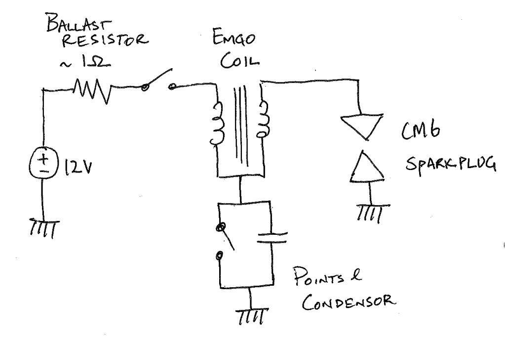
The last picture is the schematic for the transistor circuit I use on all my engines. I do not know who made this design as I was given this many years ago. Works great. If anyone is interested in this circuit I will be willing to cover it in a separate post.
Hope this helps.
")