Ignition boot molding

Home Model Engine Machinist Forum

Help Support Home Model Engine Machinist Forum:

This site may earn a commission from merchant affiliate links, including eBay, Amazon, and others.

GailInNM

Administrator
Staff member
Administrator
Global Moderator
Joined
Feb 17, 2008
Messages
2,326
Reaction score
440
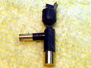
There has been a lot of interest lately on making boots for terminating ignition wires at the spark plug and distributor. I will describe one way of doing it using silicone mold making putty in an aluminum transfer mold.

For those not familiar with what a transfer mold is, here is an edited excerpt from Wikipedia. It has been edited to just the essentials for what I will be describing.

http://en.wikipedia.org/wiki/Transfer_molding
"Transfer Molding is having a "piston and cylinder"-like device built into the mold so that the rubber is squirted into the cavity through small holes.

A piece of uncured rubber is placed into a portion of the transfer mold called the "pot." The mold is closed and under pressure the rubber or plastic is forced through a small hole (the "gate") into the cavity. The mold is held closed while the plastic or rubber cures."

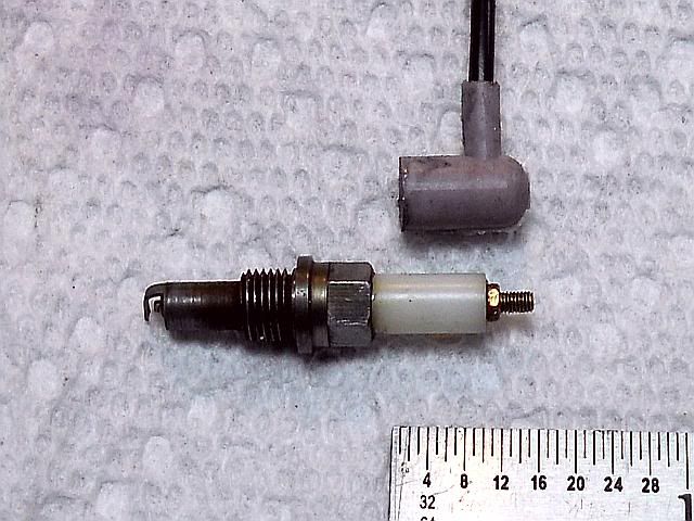
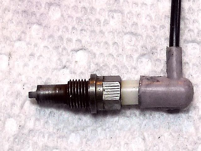
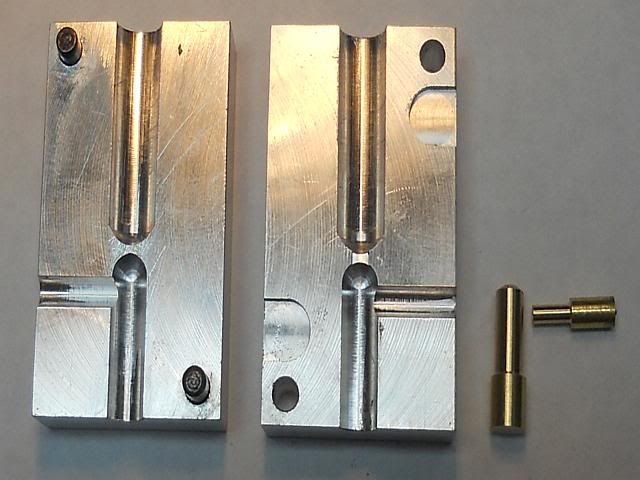
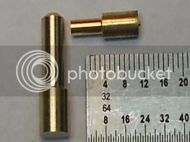
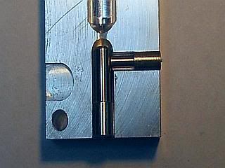
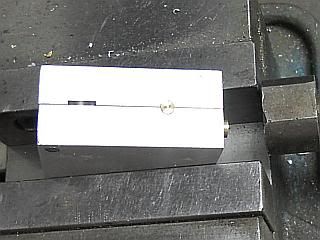
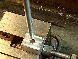
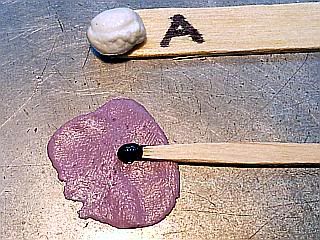
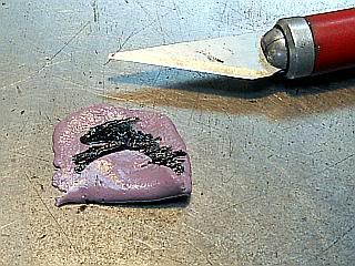
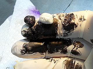
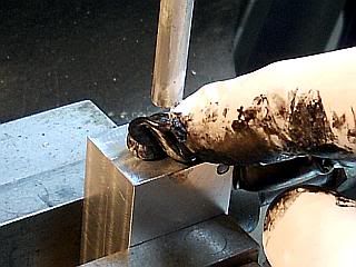
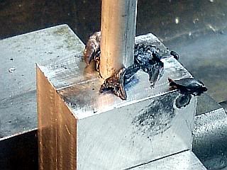
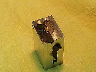
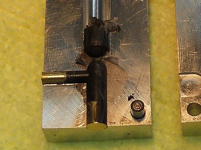
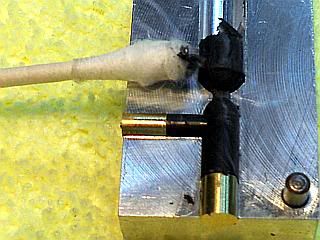
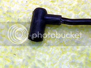
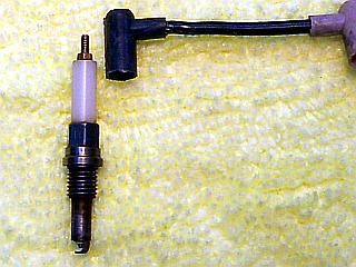
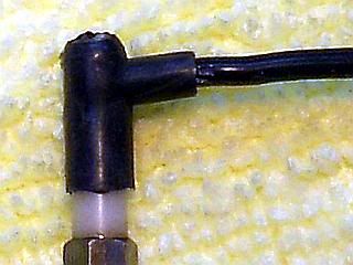
Starting with a finished spark plug boot and mold used to make it here are three photos. Then I will go through the process in some detail. For a sense of scale, there is a scale in the first photo. Additionally, the spark plug thread is 10-40 and the wire terminal on it is 0-80. The mold dimensions for each half are 1.0 x 1.625 x.375 inches.

Gail in NM

Plugboot-0001.jpg


Plugboot-0002.jpg


Plugboot-0003.jpg


In the mold photo above, the channel leading down from the top is where the raw material is placed. The cavity at the bottom is the actual mold and has the two inserts, or cores, shown on the right side of the third photo and below. They are inserted into it before the mold is closed.

The large core forms the inside of the boot and the small core the passage for the wire. The part of the cores that is held in the mold needs to be a close but free fit in the mold. The air trapped in the mold needs to be able to get around the core when the rubber if transferred into the cavity. No major problem as the rubber will be at about 500 PSI pressure. The small core is for the wire. I am using silicone insulated test lead wire that is 0.082 inch diameter, so I made the core for it at 0.076 inch diameter. Makes a snug fit when assembled. The large core is 0.150 diameter on the working end to fit my spark plug insulator which is 0.156 inch diameter. The large core is positioned in the mold so the end is flush with the bottom of the mold. The small core for the wire is pushed up against the larger core pin and needs to protrude some, say 0.020 from the side of the mold. It will be held in position when the mold is clamped up.

The notches on the side of one of the mold halves are to insert a screwdriver into to separate the mold halves after molding. They are not necessary with the material I am using, but may be if using a molding material than sticks more. Two 1/8 inch diameter alignment dowels are pressed in to one half of the mold and a slip fit matching holes are on the other half. I used 0.127 inch for them. The cores will help align the mold halves also when assembled.

On one half of the mold the transfer passage is cut between the material chamber and the mold cavity. I milled this one 0.094 wide and 0.012 inch deep. The dimensions are not critical. If you make it too thick then it is more work to remove the gate from the finished part, but it should be at least 0.006 deep.

Plugboot-0004.jpg


Plugboot-0005.jpg

 
A word about materials.
My molding compound of choice is Quick-Sil. It is a two part fast setting silicone putty used in the jewelery trade and is available from many jeweler supply firms and on the ebay at sometimes astounding prices.

For small quantities Esslinger is good. A 3 ounce package is about $US9 and if you select USPS shipping the shipping is under $4.
http://www.esslinger.com/quick-silrubbermoldsiliconecompound-3oz.aspx

Micro-Mark carries it under their own brand name in 1 pound kits for about US$30.
http://www.micromark.com/Silicone-Putty-1-lb,7853.html

It is very safe to use and is sometimes used for making candy molds. Here is the MSDS sheet on it.
http://www.castaldo.com/pdfs_msds/qsilb_msds.pdf

The first two photos show it molded without any coloring. I will show how to make it black a little bit later, but I use a paste black colorant that is made for urethane resins. I don't know who made it. I have a 4 ounce jar of it that I have been for 15 years and the label has fallen off. You don't need much. My jar still looks full. But, any pigment made for epoxy, polyester or urethane resin should work fine. Probably some artist's oil paint would work, but I have never tried it. Any oil based pigment should work OK. Water based pigments will not work.

The following from Micro-Mark should work fine.
http://www.micromark.com/Black-Opaque-Pigment-1-oz,7901.html
This pigment does not work.
stevehuckss396 tried it and the silicon would not set up

http://www.homemodelenginemachinist.com/index.php?topic=9609.msg159224#msg159224
See post #26 this thread.


There is no electrical data available on Quick-Sil. Some have questioned the use of black pigment about degrading the insulating qualities of it. My off the wall test show no problems. I molded some Quick-Sil to about 0.010 thick with about 3 times as much pigment as I would normally use. After curing, I put it between my finger and the top of the spark plug on one of my running engines with another finger of the same hand touching the frame and felt nothing. I wrapped the spark plug insulator with the same sheet making contact with the wire end and the body and there was not effect, so I am not worried about it.

One thing about Quick-Sil that is nice is that I will not stick to anything and after cure nothing will stick to it.

For silicone insulated ignition wire, there are a lot hobby shops that have it for wiring model aircraft as the high strand count in the wire is very resistant to vibration. It is made for test leads on electronic test equipment. The wire I am using is from Testpath. I have used both 21AWG wire and 24AWG wire. I am using 21AWG wire in these photos. This is what I am using. But, you can use any wire you want. Just size the mold core accordingly.
http://www.testpath.com/Items/Silic...WG-040mm2-100-Strands-Black-33-ft-123-112.htm

Gail in NM
 
Like most machining operations there is no "right" way to make the mold. It depends on what tools you have on hand. I used ball end mills to rough things with and since I know that they will be slightly undersize I reamed the three holes with the mold assembled and clamped together. On the cavity I used a 3/16 reamer and set it to just reach the center of the ball end by eye. The wire core hole was just reamed through with an 1/8 inch reamer to the center line of the cavity and the material pot was reamed until i felt some resistance.

If you don't want to use ball end mills, everything could be drilled and reamed. You will end up with a point on the top of the finished part at the gate, but that would be easy to trim off to square it up.

After the mold halves are finished, the core pins can be made. Everything is straight forward, but remember to leave some stock sticking out, 0.020 or more, on the core pin for the wire when it is touching the cavity pin.

Gail in NM
 
This is Awesome!!!! getting the popcorn!

Always wanted a blow by blow of this process....Thanks for venturing forth Gail!

:bow: :bow:
Dave
 
With the core pins in place, assemble the two mold halves. Don't be too concerned about the position of the core pins. The large one may slip up into the mold a little bit, but it will be pushed into place when the mold is filled under pressure. The small one for the wire will be pushed up against the larger one when the mold is clamped into the vice.

One final part is the plunger that compresses the material in the mold. In this case I just used a 1/4 inch rod that I polished down a little bit so it would slide into the mold. A small chamfer on the working end is helpful to get the rod started into the mold. The rod should be fairly long, mine is about 6 inches, so it can flex a little bit in case it is not perfectly aligned to the mold.

The assembled mold is installed in the milling vice that has a stop that can press against the protruding core for the wire. The mold is pressed down to the bottom of the vice and that holds the cavity core in place. and pressed against the stop to keep the wire core in place. Clamp the mold in the vice firmly. There will be considerable pressure trying to separate the mold halves when the material is transferred. Notice that no mold release was required because the Quick_sil will not stick to anything.

The plunger is held in a drill chuck in the spindle of the mill. It is aligned to the hole on the mold so it enters smoothly and when retracted there should be at least 1/2 an inch clearance to expose the hole so material can be put in the mold.

Plugboot-0006.jpg
Plugboot-0007.jpg
 
Thanks Dave.

Now we are getting to the good part and can start making a part instead of making a tool.

Dig out about a 5/16 diameter ball of each part (A and B) of the Quick-Sil. I use a wooden craft/pop stick. Be sure to use different ends of the stick for each part or better use two sticks. You must be careful not to comtaminate the two parts with each other. The mix ratio is equal parts of both parts, but it is not very critical so eyeball accuracy is plenty good enough.

If you are not going to color the part, you can skip the next couple of steps and just mix the two parts, but read through the mixing procedure at the end of this post. I use a disposable latex glove if I am going to use colorant. It washes up easily enough, but it is messy.

I press the B part out to make a patty and then put the colorant on it. The photo shows about4 times the amount of colorant that is necessary. About two fly specks is enough and you can add a little more if it is not dark enough. At this point it needs to be on the dark side as it is going to be mixed with the white part A later. I roll up the patty with a knife blade and then knead the part B until it is a uniform color.

Now you have to work quickly. From the time you start mixing the parts A and B there is only about 2 minutes until the material starts to set. I use a 45 second mixing time as my goal and that gives me plenty of time to load it into the mold. If it is not perfectly mixed the part will probably still turn out OK as there will be a lot of turbulence in the material when it goes through the thin narrow gate into the cavity. I did not try to take a photo of mixing the two parts as the colorant shows not respect for pretty camera parts an of course time restraints on mining.

Plugboot-0008.jpg
Plugboot-0009.jpg

Plugboot-0010.jpg
Plugboot-0011.jpg

Plugboot-0012.jpg
 
Now, working quickly, press a good portion of the mixed material into the hole on top of the mold. I get about 1/2 of it in and call it good. Lower the quill to start transferring the material into the cavity. As you lower the quill you can feel when the air has been forced out of the material and then the handle moves slowly as the material is transferred into the cavity. Then there will be as lot of resistance when the cavity is filled. It will not take a lot of pressure on the quill handle as it probably has at least a 10 to 1 leverage advantage from the handle to the quill and then with a 1/4 inch rod being about 1/20 of a square inch there will be about 200 PSI of pressure in the mold for every pound of pressure you put on the quill handle. I put about 5 pounds of pressure on my quill handle, or about the same amount as I use to drill a 1/4 inch hole in mild steel.

After the resistance is felt, hold the pressure for a few seconds and then lock the quill. Gather up any material that did not make it into the hole and roll it into a ball and set by the mold. You can press on it to get an idea of how the material is setting up in the mold. If you are using colorant get rid of that nasty glove.

Go read your email, sweep the floor or pet the pooch for about 10 to 15 minutes.

Gail in NM

Plugboot-0013.jpg
Plugboot-0014.jpg
 
Gail,
Thanks so much for starting this thread. There has been quite a bit of talk about it and I'm glad you came forth with the tutorial. I for one will be giving it a try, not just for plug boots but some other things I've had in mind.
George
 
The moment of truth. Retract the plunger and remove the mold from the vice. If you have pressed too hard on the quill (just to make sure) then some rubber will have squeezed out as in the photo. Just rub it off with you finger. The colorant will be bound when the rubber sets so your fingers should not get dirty.

Open the mold and there will probably be flash around the edge of the part. It will be thin and easy to remove while the part is still in the half of the mold it stayed with. I just go around it with a cotton swab and rub it to remove it.

Now remove the part from the mold and trim the gate while the cores are still in. They can be put back in easily if you do take them out. I use fluch cutting wire cutters but a sharp knife also works well. If you want a flatter top you can trim that with a sharp knife.

Gail in NM

Plugboot-0015.jpg
Plugboot-0016.jpg

Plugboot-0017.jpg
Plugboot-0018.jpg

Plugboot-0019.jpg
 
If there is any flash around the cores, it should rub off easily before you remove the cores.

After removing the cores there will be a little bit of flash in the bottom of the hole for the wire. I did not contour the end of the wire core, and it really would not have mad much difference if I had done so. I just run a drill bit the size of the wire in by hand to rupture this thin membrane.

Prepare the spark plug wire by stripping off about twice as much insulation as the diameter of the spark plug insulator. In this case about 0.3 inch for the .156 insulator. gently twist the wires together loosely so they will enter the hole in the boot easily. push the wire in twisting the same direction as you twisted the wire until the wire hits the far wall of the insulator cavity. Then start twisting the opposite direction as you continue to feed the wire in until the insulation of the wire is up to the cavity. This will form a fuzz ball on the end of the wire. The wire I use has 100 strands so it fuzzes up nicely. Then when the spark plug is inserted it can't help but touch a few dozen of these wires. Also when the plug is inserted it locks the wires in place so the wire does not pull out. It would be possible to fish the wire through and put a split brass clip on it a pull it back into place I suppose, but I have not done so.


Plugboot-0020.jpg
Plugboot-0021.jpg

Plugboot-0022.jpg
Plugboot-0023.jpg

Plugboot-0024.jpg
 
Epilog:
I hope you find this technique useful. The same principle can easily be applied elsewhere. I did not include a dimensioned drawing of the mold as most everyone will have different requirements and I think that there is enough detail. I can prepare some drawings if anyone thinks they need them, but I would rather be building toys.

Other materials can be used if precautions are taken. If the mold is built with screws to clamp it and provisions are make to hold the cores in place and a screw down plunger is used, then heat curing materials can be used and the mold heated to cure them while under pressure. I have used rubber scrounged from tire recapping shops many years ago. That makes for a really tough rubber part. Rigid materials, such as filled epoxy putty will work well also, but you probably will have to make provisions for knock out pins in the mold, taper the cores and put draft in the mold. In almost all cases a mold release will have to be applied to the mold to be able to get the part out.

Have fun,
Gail in NM
 
Gail

Thank you so much for that excellent tutorial on making spark plug boots. One should have no problems adapting that to any similar item to be moulded that way. :bow: :bow:

Cheers :)

Don
 
That was awesome Gail...and as I can see quite a bit of work!

Thank you for your selfless effort to share with others your knowledge and talent!

:bow:

Dave


Thanks for taking the time to put this tutorial together Gail.

Great job!

 
Thanks Gail. A really great tutorial. :bow:
 
Very neat.

I can see most HMEM members busy this weekend making spark plug moulds.

Dave.
 
Back
Top