I may design an I.C. engine---

Home Model Engine Machinist Forum

Help Support Home Model Engine Machinist Forum:

This site may earn a commission from merchant affiliate links, including eBay, Amazon, and others.
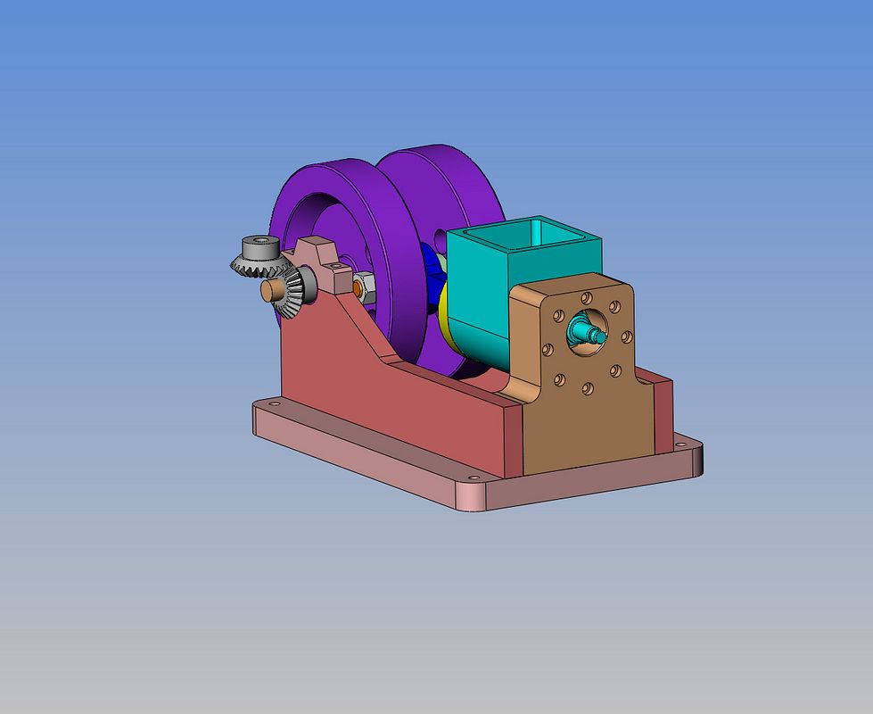
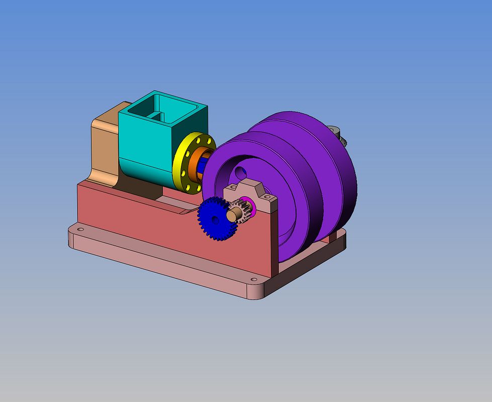
Okay---Now we're cooking!!! We got gears!!! The bevel gears are 24DP x24 teeth x 1" p.d. I have taken a good hard look at this thing, and at the size we are dealing with here, there is just no way to get the timing gears and the governor gears all on the same side of the engine. That's okay though. It makes the engine look more balanced with the governor on the opposite side. Of course this means I will have to run a pivot shaft across to the other side of the engine to latch the exhaust lifter rod, but I don't see that as a problem. The spur gears are 15 and 30 teeth 24DP x 1/4" wide, much the same as the Odds and Ends engine, just 1/16" wider.

 
Last edited:
Now this, my friends, is where it begins to get rather exciting for me!!! The governor balls are 5/8" diameter, and there will be 3 of them. I could get away with two, but I like the look of three better.
 
So here we have the three 3/8" ball bearings for the Rupnow Engine. I know they have seals in them right now, but if I find that they give too much friction, I can pop them out with a jackknife. The part that really rocked me though, was the price of the bevel gears. In the background behind the bearings you will see a governor I built a few years ago. The two new bevel gears I require for the new governor are the same size as the large gear on the existing governor, at 1" p.d. . First place I called (Stock Drive Products) wanted $35 each, in steel. The second place I called (Applied Industrial Technologies) wanted $75 each in steel. the place where I downloaded the solid models from (Rush Gears) has a minimum charge of $1300 and only produce and sell in batches. I can't buy from McMaster Carr --they have stopped selling/shipping to Canada as of about 5 or more years ago, unless you had a pre-established account with them. Fortunately one of my friends owns a company that does have an account with them, so he ordered me two steel gears at $21 each. I have seen posts where people on the forum have machined their own bevel gears successfully, but I think that is beyond my machining capabilities at this point. I will however, cut the spur gears for the cam timing myself.
.
 
And if you wondered about the governor---this explains about 50% of it. The other 50% is what happens between the end of that vertical pushrod and the exhaust valve lifter rod.
 
Its time to bite the bullet as far as valves are concerned. I have a 7/8" bore engine and a 3/4" bore engine both with 1/4" valves and .093" stems. They work well, but I find it very difficult to work with that size of valve because they are so small. I have two 1" bore engines with 10mm and 3/8" valves with 4mm and 1/8" stems, which are great to work on but MIGHT be a bit too much valve for a 7/8" bore engine.. I think I'm going to jump right into the middle and design up a 5/16" diameter valve with a 1/8" stem. There is no real air flow science involved with this decision.--It is based more on having a stem big enough to work on more comfortably, and a head small enough to fit the confines of my cylinder bore.
 
This has lead me a merry dance trying to fit the sparkplug, valve cages, and valves all into a 7/8" diameter circle. I made it, but it took a lot of thinking. I have attached a 3d pdf file of it. If you have the latest free edition of acrobat reader you should be able to double left click the image and rotate it in 3D.

View attachment ASSY OF HEAD CYL AND SPARKPLUG-RUPNOW.PDF
 
Clever idea on the spark plug placement. Any concern about whether the fuel/air mixture will get pushed up into that small space to get ignited?

Chuck
 
No worries Chuck. I have seen many engines run well with a very short nosed sparkplug that actually looked like it was setting back in a cave, hiding. They always fired with no problem.
 
Brian,

I've never worked with flyball governors. That video you post in another thread helped a LOT but post #64 just opened my eyes. The design is not as complicated as I was making it in my head. I have a question though, what holds the push rod up against the governor arm? There's got to be a spring some where and I don't see where one will fit in. Also, it seems as though the design possibilities of a flyball governor are limitless. How does one calculate the weight of the balls for a predetermined speed?

Fantastic work by the way! I'll probably have to build this engine out of pure respect and appreciation.
 
Last edited:
I have a question though, what holds the push rod up against the governor arm? There's got to be a spring some where and I don't see where one will fit in.

The exhaust valve spring?
 
Brian,

I've never worked with flyball governors. That video you post in another thread helped a LOT but post #64 just opened my eyes. The design is not as complicated as I was making it in my head. I have a question though, what holds the push rod up against the governor arm? There's got to be a spring some where and I don't see where one will fit in. Also, it seems as though the design possibilities of a flyball governor are limitless. How does one calculate the weight of the balls for a predetermined speed?

Fantastic work by the way! I'll probably have to build this engine out of pure respect and appreciation.
Take a real GOOD LOOK at the line of printing across the bottom of the drawing.
 
Just about done!!! Now if I just had the exhaust latch and a carb on this thing, I could start making detail drawings.
 
I need ten good men!!! I want to try something different this time. I am going to detail and build this engine. Any of you on the board who have followed my posts over the years will know that what I build works. I want 10 experienced (or semi experienced) people to build this engine with me. The plans will all be free. I will detail an alternate air cooled cylinder instead of the water cooled version which is shown. You can build it with or without the governor (although I think that may well be the most interesting part of the entire engine.) You can build it either water cooled or air cooled. I would like to get at least one builder from each of the major countries around the world. My plans will be in imperial, however, if you are an experienced enough builder to tackle something like this, doing a metric conversion shouldn't be a major stumbling block for you. If you choose to "Build along with Brian", I would like you to start a post on this forum and show us your work as it develops. I will give any advise asked for, and try to explain any weird or different "set-ups" that are required. I will be posting the drawings and pictures of my build here as I go along. If I find any errors (shudder) in the drawings as I build, I will quickly let everyone know and revise the drawing. I think this could be a load of fun. I know its summer (at least on this side of the globe) and the build may not go blazingly fast, but believe me, it will happen. Who's in????---Brian
 
I saw the note... I still don't see the spring or room for it. Will it be under the .174 - .474 rod potrusion?
 
This is what it looks like with the adjustable governor spring in place, with the red threaded tension adjusting knob directly above the spring. I modeled the spring thicker than what it will really be, so it will show up well. This set-up will let me adjust the RPM at which the governor lets the engine run. The second view is of the latch lever which interacts with the pushrod via a 3/16" cross shaft that runs from the governor side across to the pushrod side of the engine.

 
Ahhh! It's pushing right where I expected but I didn't envision the extra lever. I guess part of that will be used for speed control?
 
Its been a very long and busy day designing, and at about 5:00 PM I called it quits and went out on the back deck with my good wife to drink some wine and relax. And it was while we sat there in the afternoon sunshine, and celebrated Bacchus that I suddenly thought $#@^&---I didn't put any ignition points or cam on the damn thing!!!
 
Ate some supper and then realized I had forgotten the ignition cam and points!!! This is where solid modelling really shines. I just went into my archived files of the Kerzel engine from a few years ago, resaved the parts to the Rupnow engine file and modified the points mounting bracket.---about 20 minutes work.
 
Last edited:
Back
Top