arnoldb
Well-Known Member
- Joined
- Apr 8, 2009
- Messages
- 1,792
- Reaction score
- 12
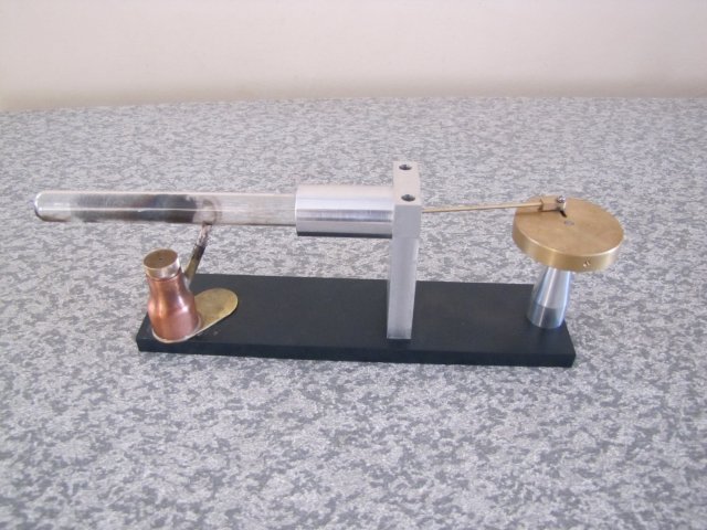
") The heading says it all; I'm attempting a Lamina flow engine.
The heading says it all; I'm attempting a Lamina flow engine. Stan did a lot of research and provided much feedback - thank you Stan :bow:
Andrew & Robert built their ones with a free dashpot sample for the piston. I can't get one, as it's for US shipment only, I'll just try and make my own, so there is the potential for total failure on this build :big:, but I'll give it a good go anyway. At least I'll be able to re-use most of the material afterward if it fails. This won't be a "pretty" engine either; as this is a very unknown area for me, I'm adding as much possibility for adjustment as possible to get it running, and the looks will suffer because of that.
I've been working on it on and off for the last three weeks; a bit of life and personal commitments pleasantly intervened, so I've not even had a chance to post up on the build yet.
I started off with this lot:
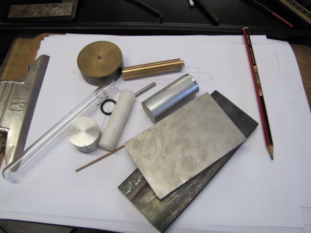
A crude drawing, and all kinds of bits 'n bobs for the base column, cylinder piston and flywheel. I have a handful of ~16mm OD Pyrex test tubes, and scrounged around for some suitable O-rings. The bit of PTFE is for the bearings.
The cylinder will be aluminium, the piston phosphor bronze, and I hope that the addition of a bit of graphite powder will make it run with low friction. I'll try PTFE for the piston as well if the phosphor bronze does not work out. The flywheel will be mounted horizontally with a "point bearing" at the bottom to minimise friction.
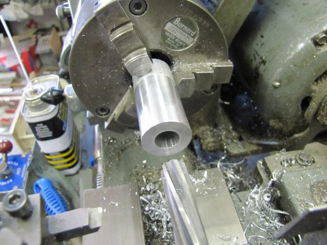
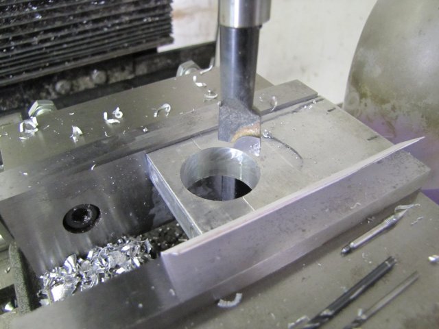
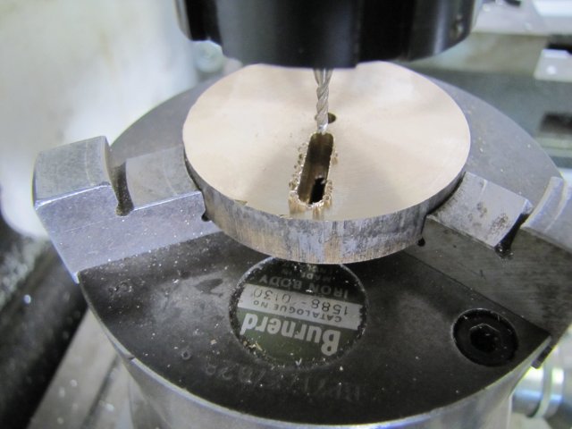
I started on the cylinder - drilled and reamed through to 12mm:
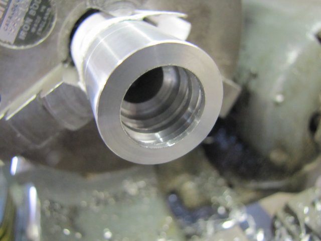
Then reversed in the chuck, and bored out to 16.6mm, and two 1.5mm deep grooves added for O-rings:
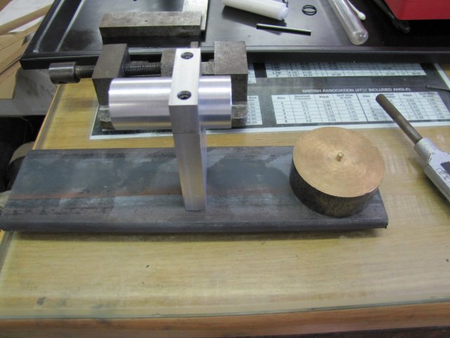
Next I worked on the column - just whittled down a block of 12mm aluminium, drilled, counter bored and tapped for fitting some 3mm cap screws, and slit the top off. Then I used a bit of thin aluminium foil clamped between the top and bottom bits to provide some spacing, and bored out a matching hole for the cylinder to just fit in the hole:
When taken apart, and with the aluminium foil removed, it will clamp the cylinder very well.
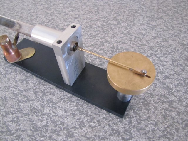
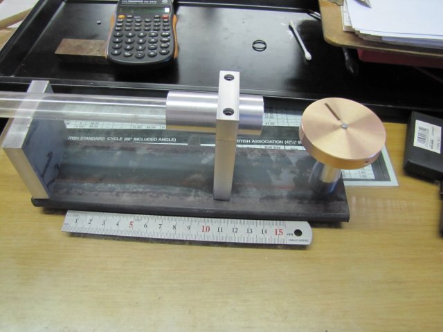
Then I did a mock-up to see where I was at:
The bit of hot-rolled flat bar for the base was a bit short, so I chucked that on the stock pile, and sawed off a longer piece; I have about 4m of this flat bar in stock.
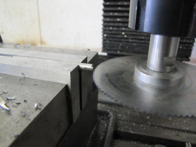
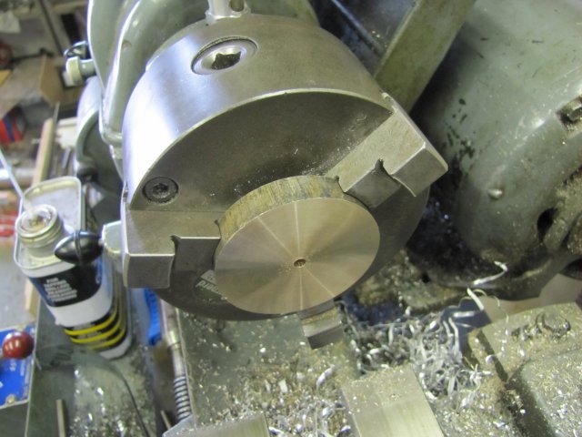
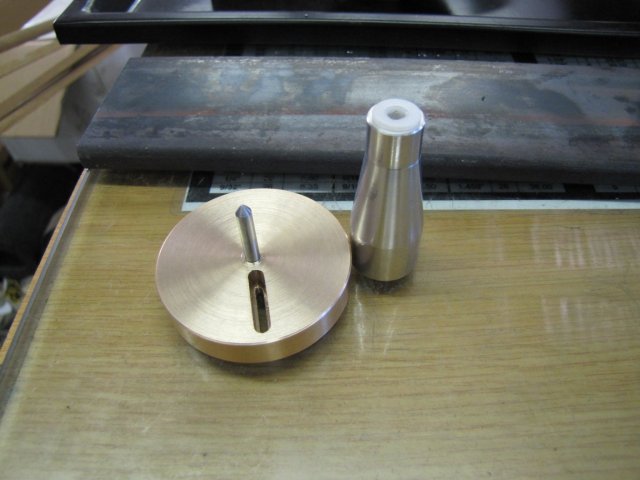
Work on the flywheel then started; the bit of bronze I had for that was much too thick, and rather than just turn it all into chips, I sawed it down the middle, and then cleaned up one face of the one section on the lathe, flipped it and faced the other side to make it 10mm thick and drilled and reamed for a 4mm axle:
Off to the rotary table on the milling machine; not to use the RT though; its just a convenient way to hold the workpiece on mill - and milled a 4mm wide slot 8mm deep into the workpiece:
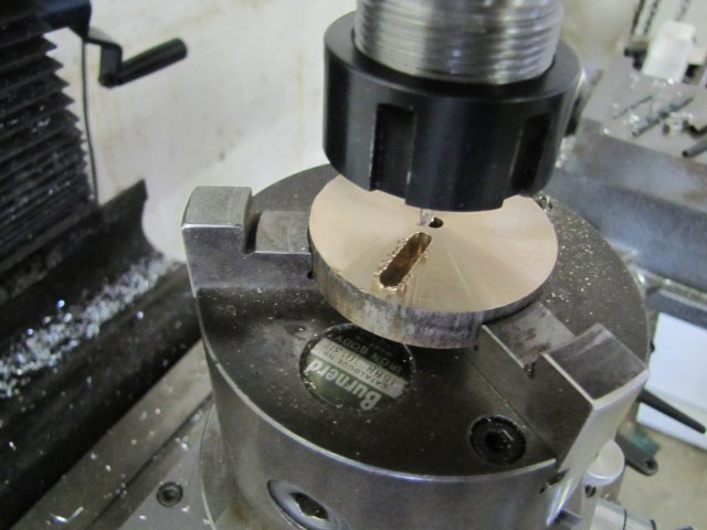
Then I milled a 2mm slot all the way through:
This gives a convenient way to adjust the crank throw; the 2mm nuts I have are 4mm across flats, so I can make a crank pin that can be easily adjusted while "hiding" the big slot at the bottom of the flywheel. The removed material will also act as a counter-balance for the piston and connecting rod.
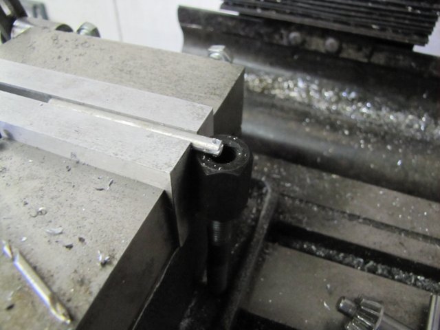
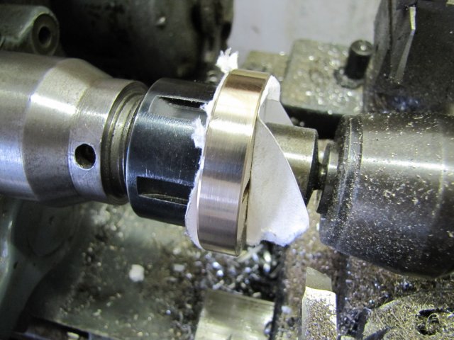
I just skimmed the gory bits off the rim of the bronze by using friction drive with a bit of 4mm rod chucked up in the collet chuck and using old business cards and tailstock pressure to keep the flywheel in place. It needs light cuts and a sharp tool for this; phosphor bronze is a bit tougher to machine than brass or aluminium, and will work-harden if the tool is blunt:
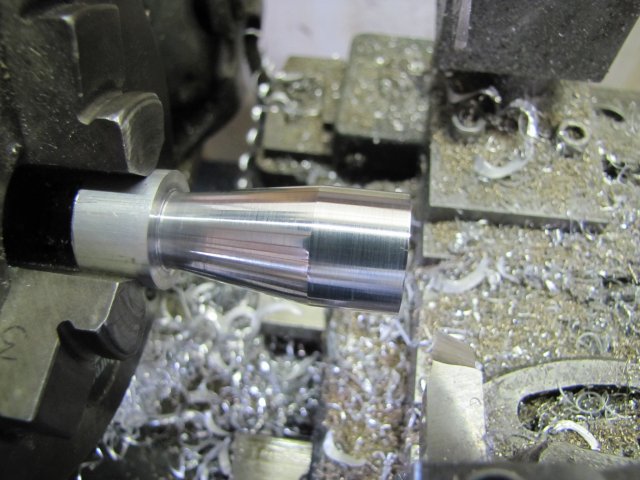
Next some work on the bearing column - just a rough turning, drilling and threading operation - drilled all the way through at 4.2mm and tapped M5 for mounting, then a bit of taper added for some visual appeal:
That was then flipped, and drilled 8mm to leave just a 10mm section of the 5mm thread.
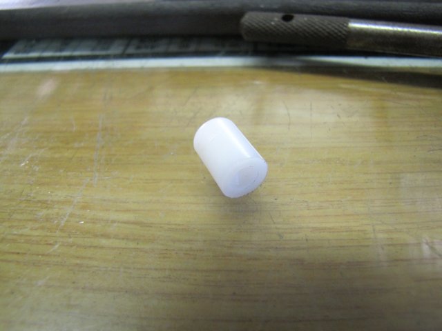
A section of the PTFE was turned down to 8mm to fit in the column, then drilled 4.5mm but not all the way through. This gets shoved down the bearing column. The cone left by the drill point forms the "point bearing":
Next I turned up the top bush for the man axle from PTFE and pushed that into the bearing column as well. A bit of 4mm silver steel with a polished taper on the end and inserted in the flywheel forms the main axle:
Another quick look-see to determine mounting points:
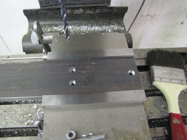
The base drilled and counter sunk and counter bored for the different mounting points - I just dug through my fasteners for available screws, so it will get a mix of a 5mm countersink screw for mounting the bearing column, and 4mm cap screws for mounting the cylinder column:
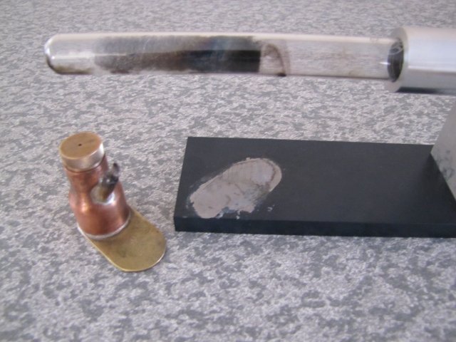
The flat bar for the base was full of dings and mill scale and crud, so I did a quick and dirty fly-cut across the face and edges to make it a bit more presentable; it will get painted so I didn't go for a terribly good finish:
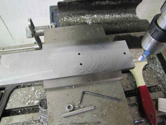
The long overhang of the workpiece on the left of the vise is because the vise is mounted to the right on the mill table. I was in no mood to reposition the vise, as that entails tramming and so on. The finish on the workpiece is cosmetic, and as the bar is 10mm thick, flex wasn't a problem.
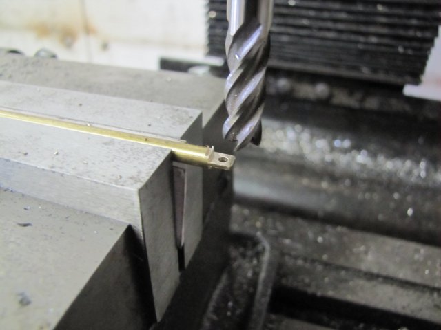
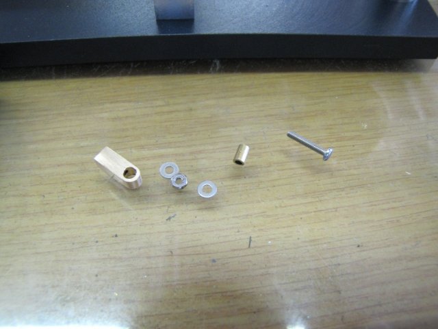
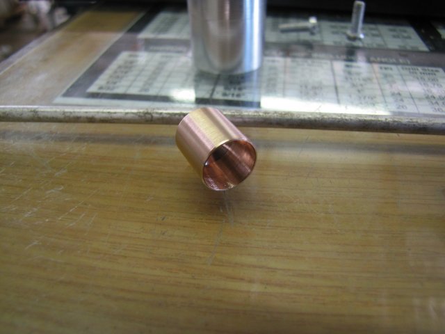
Next up was the piston; also from phosphor bronze. First I drilled it out 11mm diameter 12mm deep, then 2.5mm diameter for another bit and threaded M3, and partially parted it off. Then turned the OD to 11.98mm - taking care to get a good finish:
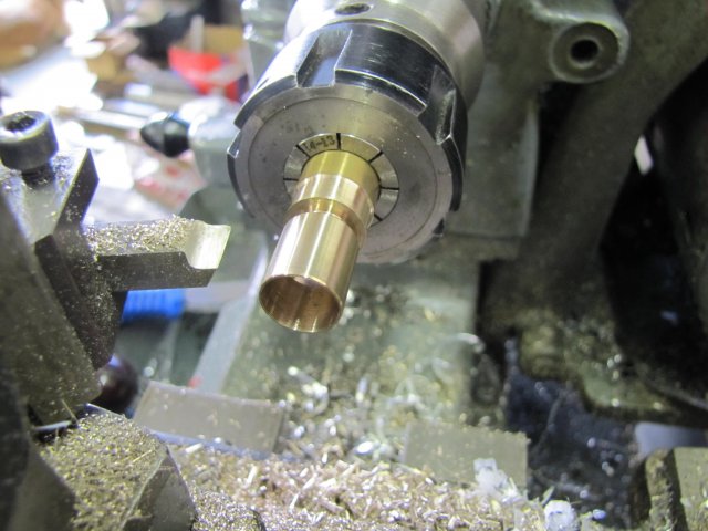
The parting cut was then finished, and I ended up with a reasonable piston:
More to follow; this post is a bit long already :hDe:
Regards, Arnold