


44-henry
Well-Known Member
- Joined
- Dec 5, 2008
- Messages
- 62
- Reaction score
- 22
Howdy,
Not sure if this is a good place to post this as it is a bit off topic for the forum, but it is machining related.
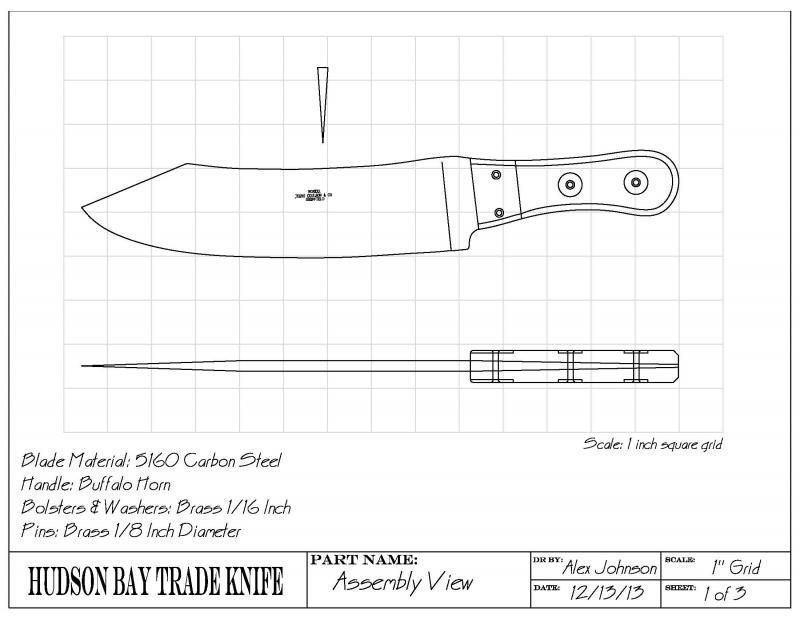
Just before Christmas I had a friend ask me if I could build a reproduction of a Hudson Bay trade/camp knife for him to use at reenactment events. Not knowing much about the knife I agreed, perhaps a bit too quickly. Once the promise had been made I needed to learn as much as I could about these knives. Quick research showed that they were produced by a few English makers for the Hudson Bay company who sold them from about the mid 1850's until the beginning of the 20th century. Though there appear to have been some variances, basically this is a large knife that was used for multiple purposes from chopping wood, butchering large animals, food preparation, and probably personal defense. The knife typically was about 13.5 inches long and a hair over 2 inches wide at the widest point. The handle tang had a reverse taper on it. The spine of the knife was around .25 inch thick and tapered to the end. Handles were almost always buffalo horn with brass bolsters and washers.
After examining several models that I found photographs with online I looked for a suitable set of drawings for the knife. I found a few, but there seemed to be differences from the drawings and the photos I was finding, so I decided to recreate a drawing using a Jukes & Coulson version from photos I found online. The drawing below is what I came up with.
Here is one of the original photos that the drawing was based on.

I have made some revisions to the drawing since this point based on information I received from others on the topic. The main change is that the handles on mine taper to fit the tang, but on the originals it would appear that the handle slabs are constant thickness. The handles also have a slight forward bevel at the end. These are changes that I will be making to the finished knife.
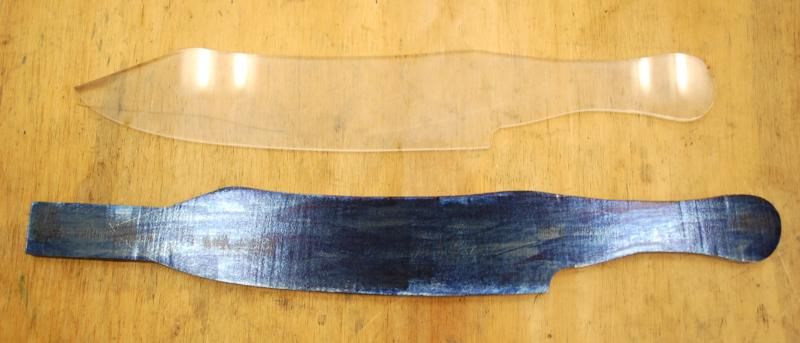
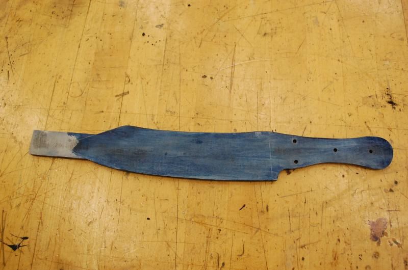
Once a pattern was in hand I cut a piece of 5160 carbon steel that I had to the appropriate dimensions on the band saw using a plastic template as a guide. I left an extension on the end of the blade to assist in clamping the blank to an angle table that I am using to cut the deep bevels in the blade.
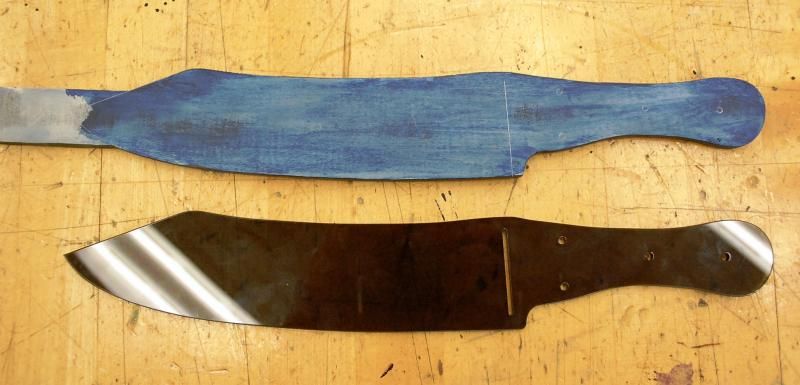
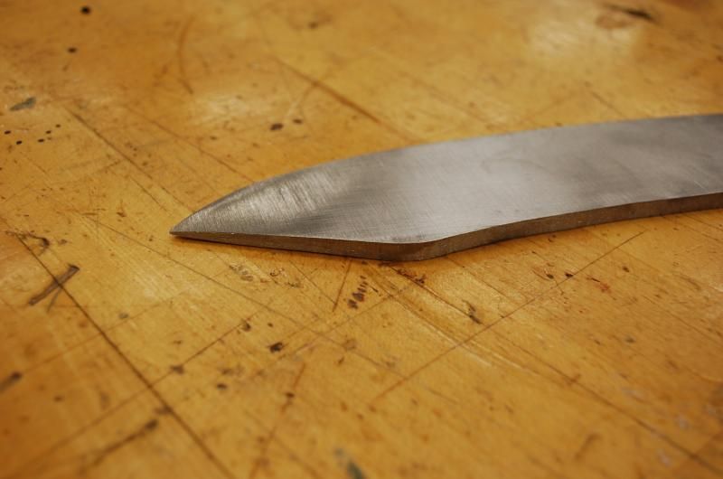
It is difficult to tell from photos what the actual cross section of the blade would look like. Some think that it is a flat grind, others that the blade is more convex. I chose to go kind of in between, in other words a very slight convex form that tapers uniformly from the front of the bolsters to the blade tip.
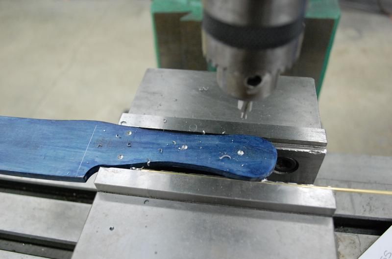
Before mounting it the mill I wanted to drill the holes for the handle and bolster pins and figured it would be easier to accomplish this before the tang was tapered. I cut out a template that had the holes placed in the correct position and also put in a feature to mark the ricasso edge where the plunge starts. I later moved this up a bit from the mark on the blade.
The holes were marked and the locations spotted with an optical center punch.
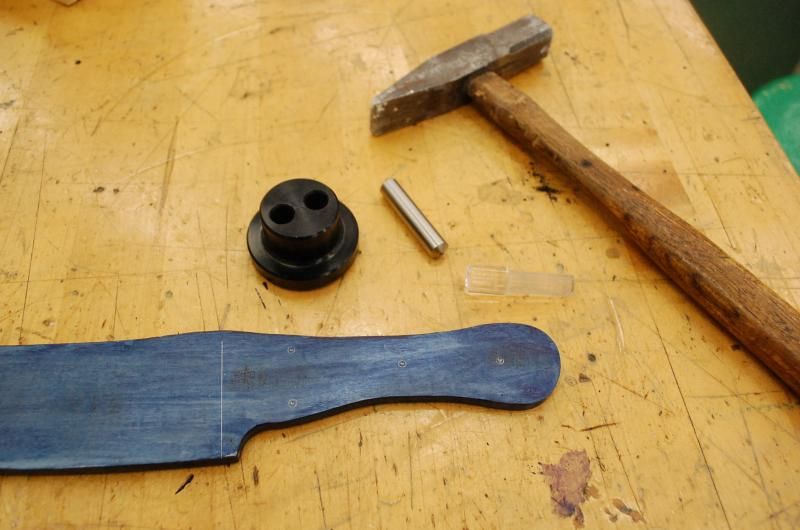
Following this I center drilled all the holes on the milling machine. The handle is a strange contour and does not lend itself well to clamping in the vise, a small brass rod helped to even the pressure for drilling.
Next the holes were drilled with an 1/8" bit.
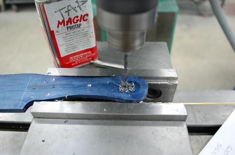
Following this the blank was deburred for the next operation, the holes were all chamferred with a hand drill and countersink bit.
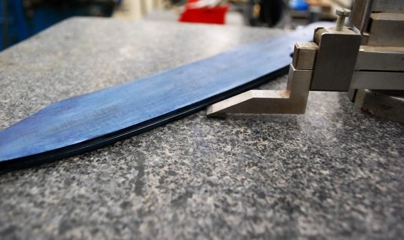
Lines were scribed along the center line of the blade edge. I wanted to leave a flat about .030 wide until after the blade was heat treated. This would be reduced down to about .015-.020 during the rough grinding, but before heat treatment. I used a surface plate and height gauge to scribe the lines after the blade was coated with layout dye.
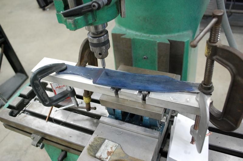
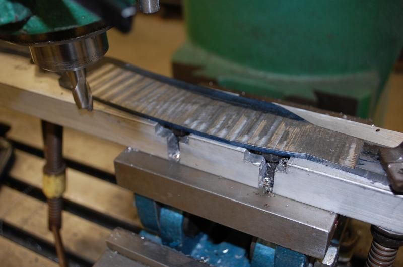
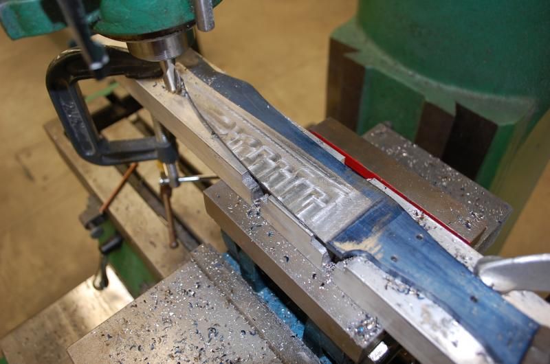
This is my tooling plate mounted on the angle table. Though I have a belt grinder, I felt it would be easier to remove the large amount of material with the mill rather than grinding. This also proves to be more cost effective as I can sharpen end mills, but haven't figured out a way to sharpen a belt yet. Using the mill also helps to keep both tapers uniform and symmetrical. The process starts by clamping the blade to the angle table and lining up the ricasso line with the table travel. I used an edge finder and adjusted the blade until I could follow the line. In this case I simply used c-clamps to secure the blade to the table. Two clamps held the blade down, another two provided stops on both sides of the blade to help resist the forces of machining. The blade could also have been screwed down, as was my original intent, but I would have had to shifted the blade a couple times per side so I didn't go with this option.
The tooling plate is a large chunk of extruded aluminum that I had handy. As long as it is large enough to accommodate the blade blank and flat anything would do.

 [/IMG]
Setting the appropriate angle is a matter of trial and error. I used the guidelines that I had scribed and also a line I scribed parallel with the back edge of the blade at .300 inch to guide me. Once the angle was found, ssing small bites, the surface was gradually milled out.
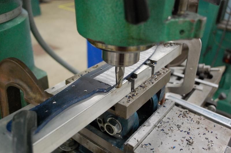
Because the blade curves the material removed is not uniform at all spots.
This necessitated shifting the blade a bit halfway through the process to account for this.
I used the guidelines that I had scribed to serve as a guide during the machining operation.
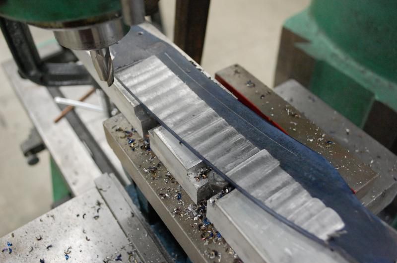
One side complete.
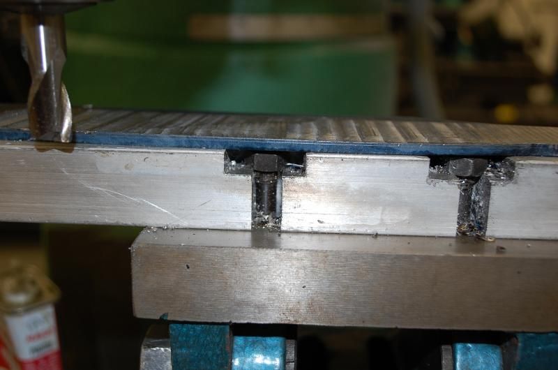
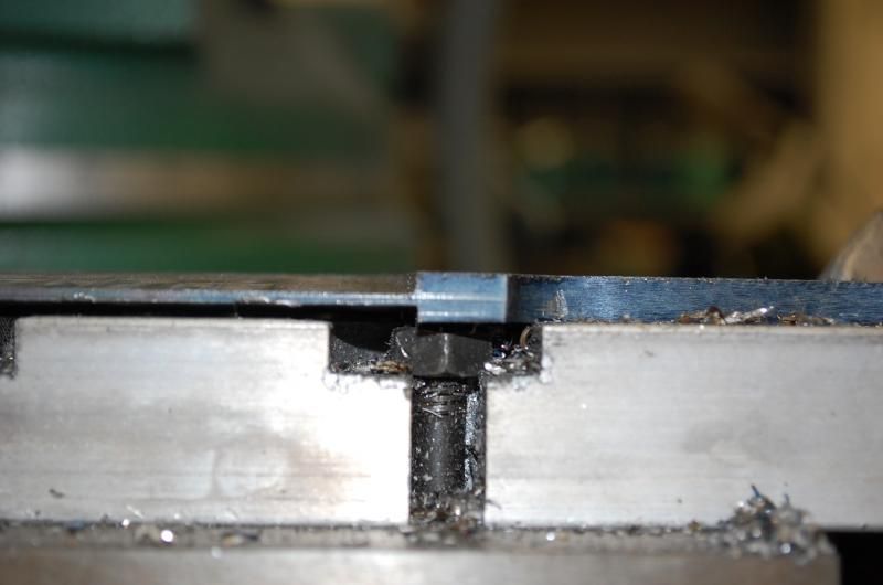
The blade blank was removed from the fixture and the location where the bevel ended in back of the spine was checked with a caliper. The setting on the caliper was locked and used to transfer a mark on the opposite side of the blade. This provided a precise guideline to follow when machining the other side and would help keep the two sides symmetrical.
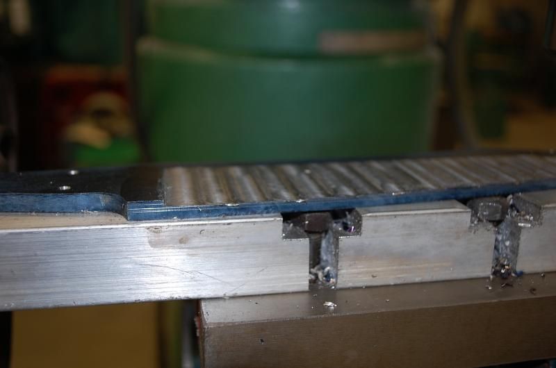
The blank was carefully deburred and mounted on the plate in the opposite direction. Once accomplished and properly aligned machining commenced.
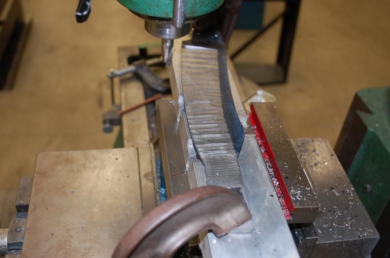
Small adjustments were made to keep both sides the correct depth and make the ricasso region match both sides. The photo below shows some adjustment was still necessary, but this was accomplished with minor changes and this area will eventually be refined with filing/grinding later on.
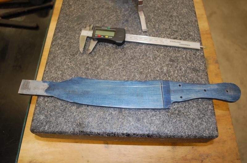
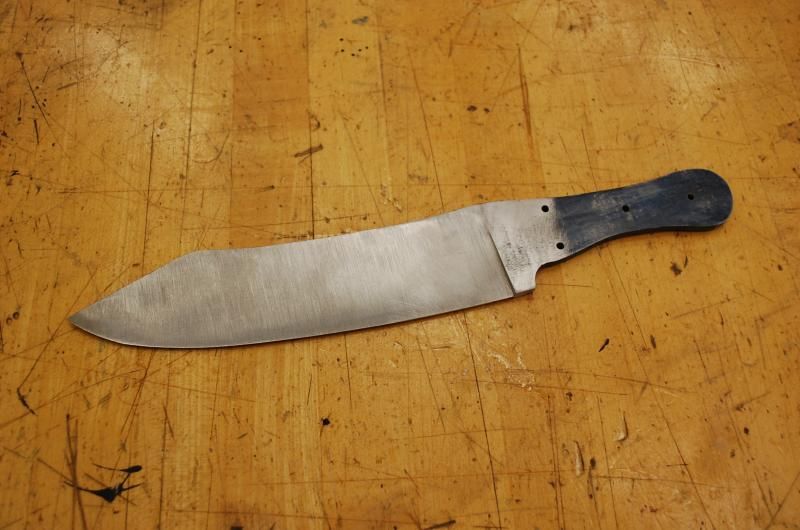
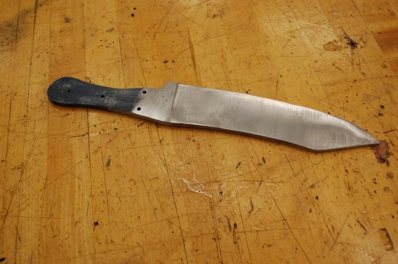
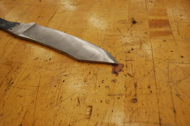
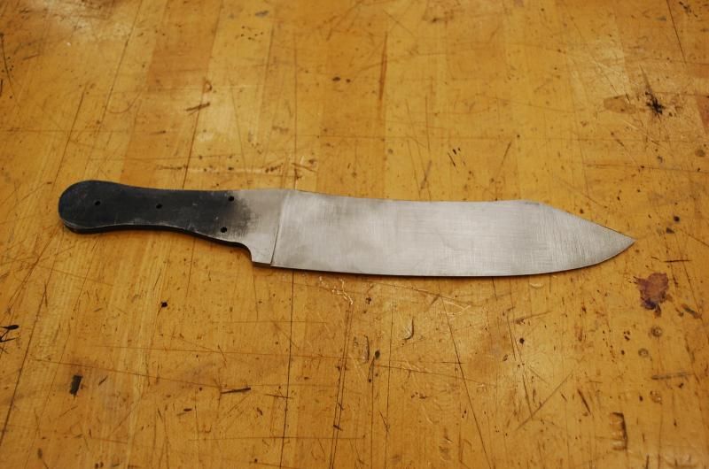
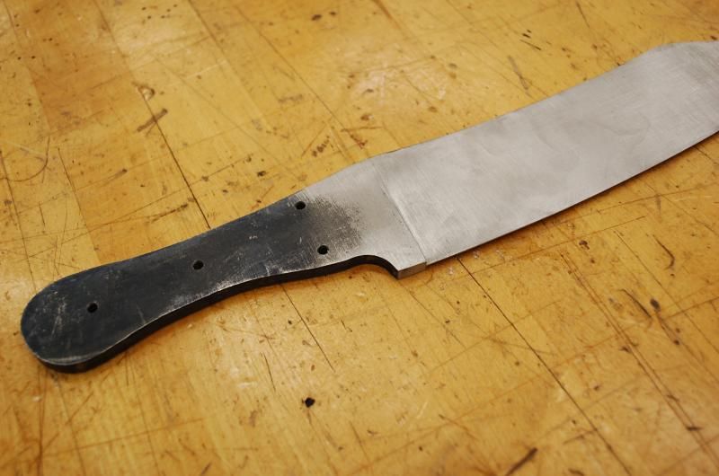
When the milling operation was complete the blade was uniform, but very rough from all the milling marks. As I did not have an extra hand to photograph me I didn't document the next few steps (still waiting for Google Glass). Basically I band sawed the additional material off the tip and than used a belt grinder to refine both blade flats and start the taper. The blade in the next few shots is rough ground. The tang still needs to be tapered.
My next steps will be to taper the handle tang. Following this the blank will be stress relieved and ready for heat treatment.
This is obviously only one method of shaping a blade. The mill does help remove material and keep things uniform, however, the final product is very much dependent on handwork to execute. As I don't make many knives this method probably seems backwards to some who do more of this type of work, but it does seem to work. Hope you enjoyed the look.
Not sure if this is a good place to post this as it is a bit off topic for the forum, but it is machining related.
Just before Christmas I had a friend ask me if I could build a reproduction of a Hudson Bay trade/camp knife for him to use at reenactment events. Not knowing much about the knife I agreed, perhaps a bit too quickly. Once the promise had been made I needed to learn as much as I could about these knives. Quick research showed that they were produced by a few English makers for the Hudson Bay company who sold them from about the mid 1850's until the beginning of the 20th century. Though there appear to have been some variances, basically this is a large knife that was used for multiple purposes from chopping wood, butchering large animals, food preparation, and probably personal defense. The knife typically was about 13.5 inches long and a hair over 2 inches wide at the widest point. The handle tang had a reverse taper on it. The spine of the knife was around .25 inch thick and tapered to the end. Handles were almost always buffalo horn with brass bolsters and washers.
After examining several models that I found photographs with online I looked for a suitable set of drawings for the knife. I found a few, but there seemed to be differences from the drawings and the photos I was finding, so I decided to recreate a drawing using a Jukes & Coulson version from photos I found online. The drawing below is what I came up with.
Here is one of the original photos that the drawing was based on.
I have made some revisions to the drawing since this point based on information I received from others on the topic. The main change is that the handles on mine taper to fit the tang, but on the originals it would appear that the handle slabs are constant thickness. The handles also have a slight forward bevel at the end. These are changes that I will be making to the finished knife.
Once a pattern was in hand I cut a piece of 5160 carbon steel that I had to the appropriate dimensions on the band saw using a plastic template as a guide. I left an extension on the end of the blade to assist in clamping the blank to an angle table that I am using to cut the deep bevels in the blade.
It is difficult to tell from photos what the actual cross section of the blade would look like. Some think that it is a flat grind, others that the blade is more convex. I chose to go kind of in between, in other words a very slight convex form that tapers uniformly from the front of the bolsters to the blade tip.
Before mounting it the mill I wanted to drill the holes for the handle and bolster pins and figured it would be easier to accomplish this before the tang was tapered. I cut out a template that had the holes placed in the correct position and also put in a feature to mark the ricasso edge where the plunge starts. I later moved this up a bit from the mark on the blade.
The holes were marked and the locations spotted with an optical center punch.
Following this I center drilled all the holes on the milling machine. The handle is a strange contour and does not lend itself well to clamping in the vise, a small brass rod helped to even the pressure for drilling.
Next the holes were drilled with an 1/8" bit.
Following this the blank was deburred for the next operation, the holes were all chamferred with a hand drill and countersink bit.
Lines were scribed along the center line of the blade edge. I wanted to leave a flat about .030 wide until after the blade was heat treated. This would be reduced down to about .015-.020 during the rough grinding, but before heat treatment. I used a surface plate and height gauge to scribe the lines after the blade was coated with layout dye.
This is my tooling plate mounted on the angle table. Though I have a belt grinder, I felt it would be easier to remove the large amount of material with the mill rather than grinding. This also proves to be more cost effective as I can sharpen end mills, but haven't figured out a way to sharpen a belt yet. Using the mill also helps to keep both tapers uniform and symmetrical. The process starts by clamping the blade to the angle table and lining up the ricasso line with the table travel. I used an edge finder and adjusted the blade until I could follow the line. In this case I simply used c-clamps to secure the blade to the table. Two clamps held the blade down, another two provided stops on both sides of the blade to help resist the forces of machining. The blade could also have been screwed down, as was my original intent, but I would have had to shifted the blade a couple times per side so I didn't go with this option.
The tooling plate is a large chunk of extruded aluminum that I had handy. As long as it is large enough to accommodate the blade blank and flat anything would do.
Setting the appropriate angle is a matter of trial and error. I used the guidelines that I had scribed and also a line I scribed parallel with the back edge of the blade at .300 inch to guide me. Once the angle was found, ssing small bites, the surface was gradually milled out.
Because the blade curves the material removed is not uniform at all spots.
This necessitated shifting the blade a bit halfway through the process to account for this.
I used the guidelines that I had scribed to serve as a guide during the machining operation.
One side complete.
The blade blank was removed from the fixture and the location where the bevel ended in back of the spine was checked with a caliper. The setting on the caliper was locked and used to transfer a mark on the opposite side of the blade. This provided a precise guideline to follow when machining the other side and would help keep the two sides symmetrical.
The blank was carefully deburred and mounted on the plate in the opposite direction. Once accomplished and properly aligned machining commenced.
Small adjustments were made to keep both sides the correct depth and make the ricasso region match both sides. The photo below shows some adjustment was still necessary, but this was accomplished with minor changes and this area will eventually be refined with filing/grinding later on.
When the milling operation was complete the blade was uniform, but very rough from all the milling marks. As I did not have an extra hand to photograph me I didn't document the next few steps (still waiting for Google Glass). Basically I band sawed the additional material off the tip and than used a belt grinder to refine both blade flats and start the taper. The blade in the next few shots is rough ground. The tang still needs to be tapered.
My next steps will be to taper the handle tang. Following this the blank will be stress relieved and ready for heat treatment.
This is obviously only one method of shaping a blade. The mill does help remove material and keep things uniform, however, the final product is very much dependent on handwork to execute. As I don't make many knives this method probably seems backwards to some who do more of this type of work, but it does seem to work. Hope you enjoyed the look.