How to use sine bars

Home Model Engine Machinist Forum

Help Support Home Model Engine Machinist Forum:

This site may earn a commission from merchant affiliate links, including eBay, Amazon, and others.
I use sine bar magnetic chuck for lots of jobs at the surface grinder.And recently I got a nice sinebar vice thats been just right for several jobs already..
 
Rick,
Thanks for the great link...the presentation was excellent.

Cheers,
Phil
 
Sine bars are indeed handy tools. The presentation suggests the use of gage blocks to set the angle. Don't be put off if you don't own a set of gage blocks. For 99% of the work we do, a block of scrap cut to the required stack height will provide more than enough angle accuracy.

The error equation for a sine bar looks like:

Aerr = Serr/[L cos(A)]

where:

A = angle
Aerr = angle error
Serr = stack height error
L = sine bar length

As an example, take:

A = 30 deg
L = 5 in
Serr = 0.005"

Then:

Aerr = 0.005/[5*0.866] = 1.15 milliradians = 0.066 deg

This means that the angle error if you machine the stack block to be over/under by five thou will correspond to an angle error such that, if you made that error pointing a rifle at a target 100 yards away, you'd miss the bullseye by only 1.15E-3 * 3600 ~= 4 inches - more than adequate for most shop tasks.

In fact, it's very possible to make your own sine bar - although they can be had cheaply enough that it's probably not worth your while. Once made, they can be calibrated if you have access to an accurate angle plate. The procedure is analogous to the technique for measuring an angled part shown in the presentation.
 
mklotz said:
Sine bars are indeed handy tools. The presentation suggests the use of gage blocks to set the angle. Don't be put off if you don't own a set of gage blocks. For 99% of the work we do, a block of scrap cut to the required stack height will provide more than enough angle accuracy.

.

Thats a fact. Lot of times I will use either a flat feeler guage or a drill bit will be close enough instead of getting out my gage blocks.
 
An excellent knowledge tidbit. Thanks for bringing it into the spotlight, and to those who've added some practical experience to the mix.

I always wondered exactly how these were used. I knew it had to do with trig, but figured there was more to it than the Pythagorean theorem.

On a related note, it would be great if someone could snap some photos of a real-life setup using this.

Thanks,
-Sparky
 
Marv is right that commercial sine bars can be bought quite at rather nominal prices. Unfortunately most of them are too big for much of our hobby work. Fortunately they are as easy to make as they are to use, and they can be sized to fit the equipment you have. If your milling machine is properly trammed and you can space two grooves in a chunk of metal at a reasonably accurate distance apart with a ball end mill, then you are almost home free.

The distance between the grooves is not sacred, you just have to know what it is. I mostly use a sine bar in my milling vice, and it is a 4 inch vice. A commercial 5 inch bar will not fit on the bed of the vice. The rolls hang over. So, I have a set of 3 inch sine bars for it. For small angles it is easy to set one roll on the bed of the vice and put a spacer block under the other roll on the other side of the bed. I also have some 2-1/2 bars I made for my 3 inch vice that I use on my tool grinder. These bars are not of the precision that the commercial ground and hardened ones are, but are close enough for my work. Probably considerably better than 10 minutes of angle,although I have never bothered to calibrate them.

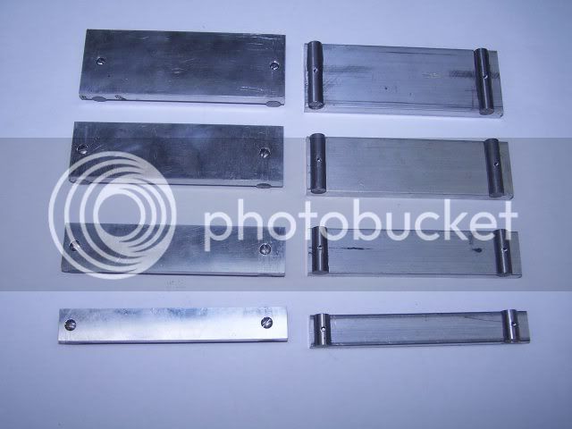
The photos show most of the details necessary. I have several of different widths to suit what I am doing. If you make some, you might as well made several as it is almost all the same setup and will save you time later. The ones in the photos are 1/2, 3/4, 1, and 1-1/4 nominal width. I say nominal because it is better to make them a little bit, say 0.010 or 0.020 inch, narrow so if you are clamping on a nominal size material you are not clamping on the bar.

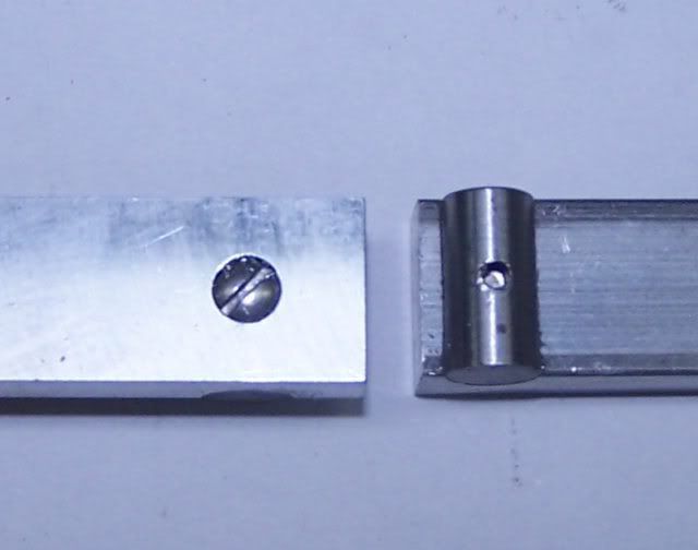
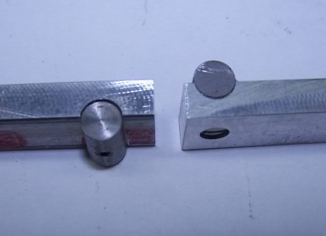
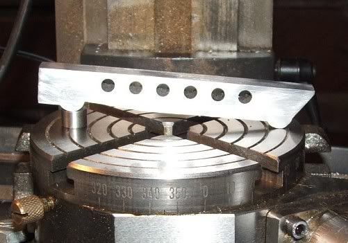
This set is made from 1/4 inch thick aluminum. The rolls are 1/4diameter 12L14 steel. Ground stock would be better, but cold rolled is adequate for me. The rolls are cut a little bit shorter than the width of the aluminum bar so they don't hang out. A 2-56 tapped hole in put in the middle of the roll. Deburr both sided of the tapped hole. The bars have a round bottom grooves milled in them to match the rolls. A clearance hole for a 2-56 screw is in the center of each groove. Putting the grooves in is the only critical measurement as the grooves must be a known distance apart. If you have a DRO fitted it is easy. If you don't have a DRO, make sure to take the backlash up by approaching each groove from the same direction.

After putting the grooves in, flip the bars over and counter bore for the screw head. Go a little bit extra deep and you are going to mill this surface after a while. Mix up a little bit of epoxy and spread a little bit in each groove, then screw the rolls in place on the bar. Put a little bit of wax paper in the bottom of your vice and clamp the rolls to the bar. The epoxy provided a bed for the rolls to seat on. All this is to insure that the rolls are parallel to each other. The wax paper makes cleaning up any epoxy that might drip easier. After the epoxy is cured, put your best set of parallels that are tall enough to bring the top of the bar above the vice jaws and tap the sine bar down on the parallels. Make a skim cut across the top and you are done.

Check with a micrometer that the distance from the bottom of the roll to the top of the bar is the same on both rolls.

Sine1.jpg

Sine2.jpg

Sine3.jpg
 
sparky961 said:
On a related note, it would be great if someone could snap some photos of a real-life setup using this.

I can oblige, from the morgue :D

simple set up in the milling vise, after closing the vise the sine bar is slid out. Not a super strong set up, but simple :) .I'm using an adjustable parallel to get the height i want.

smallsignmbar.jpg


Here's an angle block i made. well really its a square but i figured why not do the 45 accurately as well than it can be use as 45 degree angle block. Its tool steel and is being clamped to an accurate angle plate for surface grinding.

DSC_1008.jpg


the good commercial sine plates/bars are expensive - i know you get cheap anything nowadays but do you trust that stuff for precision work (which is what i mostly think of as the use of a sine bar, precision stuff)? imo a sine bar is of dubious value - unless you are doing a radically different class and type of work than I, its just not that common that a angle needs to be super precision - beyond what a vernier protractor can do. It seems most of them that i encounter are for aesthetics. Not that it isn't a good tool - it has its place as part of a complete tool kit, just that those times when you absolutely must have a sign bar are, in my experience, very far and few between making it a candidate for a 'most time spent in the draw' award.

I like Gail's home made ones for general work. Still, if its not requiring true high-quality sine bar accuracy, I mostly go to a vernier protractor like this nice old Moore and Wright.

vernierprotracter.jpg
 
Sweet... Thanks, Mcgyver.

These are the kind of pictures that'll pop into my head later when I'm standing in front of the machine thinking to myself "now how am I supposed to hang onto this piece at that angle?".

-Sparky
 
This is all good info. In this week's shop class we used angle bars to clamp a piece at 22 degrees, so that is another method. That said, I really like the vernier protractor and intend to buy one, as it looks to be the easiest method of all.

I also apreciate seeing how the V-block clamp is used in the photo, as often the sine bar/protractor/angle blocks may be thicker than the workpiece.
 
As Gail says, the standard 5" sine bar is often too long for our purposes. I have a 2.5" one I bought (probably from Enco, can't remember) but have also made my own along the same lines as Gail pictures. I didn't bother making a semicircular groove for the rollers. Just cut a U-shaped groove with a standard end mill.

If you do make one, it's worth investing in a quality angle plate to use to calibrate your homemade one. Put it on your sine bar and prop it up on a surface plate until the exposed edge of the angle plate is level as measured with a DTI on a height gage. The length of your homemade sine bar can then be found from:

L = S/sin(A)

where:

L = length of sine bar
S = stack height
A = angle of angle plate

Once L is determined, engrave the value on the bottom of the sine bar and use it when calculating the stack height for whatever angle you want in your setup.

Again, small errors in the length value cause only small errors in the angle. The error equation is:

Aerr = S/[L^2 * cos(A)]

For a 5" sine bar set to an angle of 30 deg, a 0.001" error in the value of L will produce an angle error of only 0.0066 deg.

For common angles (e.g., integer multiples of 5 deg), it's often easier to just buy a set of angle blocks from the usual suspects. They're not terribly expensive and handy as a shirt pocket. The real utility of sine bars appears when you need to produce some oddball angle - a common example is the angled steam holes in a cylinder head from the bore to the valve face.

Finally, the problem of the work being narrower than the sine bar. Make yourself a collection of "pusher blocks" from leftover bits of scrap and insert these between the work and the movable vise jaw. I made mine as half-size copies of a 1-2-3 block (i.e., they're 0.5-1-1.5 blocks) so they can also be used as calibrated spacers in other setups.

Protractors are useful but I don't like the idea of clamping work in the milling vise with no support below it (as would be necessary if milling at an angle). I've been bitten too often when I tried that which is why I always use angle blocks or a sine bar to provide support.
 
I forgot to mention that, if you're going to use a sine bar, you may find my SINEBAR program useful. It will calculate the required stack height, the error sensitivities and the gage blocks needed to form the stack if you decide to use gage blocks.

A sample output is appended below:


------------------------------------

SINEBAR CALCULATIONS

Distance between sine bar rolls [5] ?
Angle input mode [D]ecimal degrees, (X) deg/min/sec ?
angle in decimal degrees [30.125 deg] ?

Distance between rolls = 5.000000
Angle = 30.125000 deg
Stack height = 2.509441
Stack height measured in same units as roll separation.
A .001 error in the roll distance will cause an angle error of 0.006649 deg
A .001 error in the stack height will cause an angle error of 0.013249 deg

Blocks from standard 81 gage block set needed to form stack = 2.5094 in:

block = 0.1004 remainder = 2.4090
block = 0.1090 remainder = 2.3000
block = 0.3000 remainder = 2.0000
block = 2.0000 remainder = 0.0000
 
Doing a bit of math and assuming that the thinnest standard gauge block is .1", the smallest angle that can be measured with a sine bar and one block is .57 degrees (or 1.14 degrees with a 5" bar).

I then realized that smaller angles can be set by putting gauge blocks under both ends of the bar such that the difference between them is what is required.
 
One point that I have never seen described anywhere, is how do you hold the sine bar on top of the guage blocks at an angle so they are don't move and stay accurately placed while you are trying to set the angle of a angle plate or some other fixture that doesn't have a clamping jaw like a vice. You can"wring" the blocks together but everything else whats to slide or fall apart when you take your hands off to move the table. Do they have a extra arm upgrade for machinists available.
 
Loose, not sure what the grinding guys do but imo gauge blocks are a precision tool used for inspection and surface plate work - not in machining setups. You can see in my middle pic that they're being used to establish and angle but only the angle plate and work leaves the surface plate for the grinder, gauge blocks stay safe and dry :D
 
mklotz said:
I forgot to mention that, if you're going to use a sine bar, you may find my SINEBAR program useful. It will calculate the required stack height, the error sensitivities and the gage blocks needed to form the stack if you decide to use gage blocks.

Did that, but the answer, along with the window, disappear with blinding speed as soon as I press return for the final input???? Can't for the life of me figure out how to get it to hold.

Oh well, back to the tables I guess. :(
 
Tel,
This is from Marv's website-
A number of DOS-challenged users of my programs have written to complain that when the program terminates, Windoze, in another one of its mis-guided attempts to think for the user, closes the window before they can inspect the answers generated by the program. Dave Wood has spent some time working out how to keep Micro$oft's abortion from trying to outthink the user. He writes:

In Explorer, right-click on the .exe program name. Select "Properties". Select the "Program" tab. At the bottom of this dialog is a single check-box "Close on exit". Un-check this box. At the bottom of the dialog click on "Apply," then "OK".

His remarks are specific to XP but I expect they are applicable to other flavors of MS so-called operating systems.

Also, Anthony Nagy writes, "I discovered that if you create and use a shortcut to run the program it will run under Windows and not terminate. I run Windows 2000. This may also work with your other programs and other versions of Windows."

I had to put the short cut on my computer so that I could run his 3 wire program and read the last answer.
Regards,
Fred

 
Thanks Fred, I tried the shortcut route with no luck, I'll try t'other now.
 
BRILLIANT mate, works fine now!!!! ;D

Just as a matter of interest, here's my home made 3" sine bar

sinebar2.jpg
 
What do I have to do to get you guys to actually read the "Introduction" section on my webpage? Will pleading work? How about threats? :)
 
Back
Top