How to develope an angle from plan

Home Model Engine Machinist Forum

Help Support Home Model Engine Machinist Forum:

This site may earn a commission from merchant affiliate links, including eBay, Amazon, and others.
Joined
Dec 26, 2008
Messages
3,697
Reaction score
685
Location
Crewe, Cheshire, UK
I am now getting everything ready to restart in my shop, and one of the first jobs will be to make a 3 roll rolling machine.
I like to get everything ready and worked out before I start, but I have a problem with this drawing (the only one showing what this machine requires).

I have looked at this plan for ages trying to find where I can develop the angle required from, to no avail. All other required angles are shown.

The angled line is between the two red circles.

Angle%20problem_zpsfgxrdvto.jpg


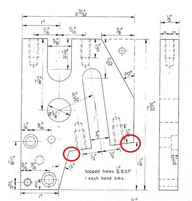
I am at a stage of mental blockage over this, so any help would be gratefully received.


John
 
Last edited:
Here is a quick drawing I whipped up.
The angles are 76.95 deg & 61.95 deg I only went with 1 decimal place on the drawing.
Hope this helps


Paul

Roller End.jpg
 
Thank you so much Paul.

Just a couple of questions, which is correct, the 79.95 in your text or the 77 on the drawing?

I see you have put 13 degs in the drawing, so I suspect it is 77 degs.

Where did you develop it from? I suspected that the circle to the right of the long slot had something to do with it, but couldn't get my addled brain around it.


John
 
:wall: 77 is correct, I corrected the post

On the drawing their is a 31/32 radius(the circle) and that radius is tangent to the centre of the slot (the line) so if you imagine putting a square with one edge aligned with the tagent line and the other edge aligned to where it intersect the 1-1/4 height you will get the angle.

I used Autodesk Inventor to do my drawings
 
Where did you develop it from?

Seems easy !?

20170131.PNG

The numbers are wrong, but:
  1. identify the point on the right side up 1,25" (in my drawing it is 25.4mm up).
  2. draw a tangential line from the circle 31/32" which is coaxial to the 5/8-circle
  3. now this tangential line has to have a perpendicular line which must go through that point on the right side.

I hope the description is understandable ?

greeting from Vienna/AT
Thomas
 
In the book, the author describes the angle as about 9 degrees
The line of the slot for the rear roller is at about 9 degrees to vertical and the easiest way to mark this out is to carry a line from the 1-11/16 inch diameter from the front (which is the centre of the latch pivot screw) to form a tangent to a 31/32 inch radius struck from the centre of the lower
roller.

HTH
 
You were not being daft. GHT's drawing does not fully define the geometry. Reading the text, you take a centre line from the top surface, 1-11/16 from the front edge (where the latch screw hole is) and tangential to a 31/32 arc centred on the lower roller bore. I usually redraw any published design using CAD before building, and my drawing shows the angle in question to be 8.88° from the horizontal. (My finished product here: http://www.hemingwaykits.com/acatalog/gallery.html)
 
Last edited:
Thank you Charles.

I read through the destructions from Hemingway, but didn't pick anything up along the way, it might have been there, but I most probably missed it. Maybe I should root out the book and read that as I know I have it somewhere.

I hope mine turns out just a good percentage of what yours has.

I will actually be modifying my version as I won't be able to carry it to my vice, so I will be fitting high feet to it to allow it to be bolted to the bench, then I will have the three machines in my metal prep room that I really do require for processing sheet metal.

John
 
I have now found the book and read the build destructions through and found the part I most probably missed in the first place if the text that comes with the kit is the same as in the book.

But anyway, I can write on the plans now and it will be ready when I am.

Thank you all who helped.

BTW, I am gradually working my way through all my kits and projects, so there might be a few more questions like this until I get my head straight.


John
 
Last edited:
Hi John,

Not quite on topic, but I came across this YouTube video and thought it might interest you. I found it facinating.

[ame]https://www.youtube.com/watch?v=EaIqlG1vHs8&feature=youtu.be[/ame]
 
That really was fascinating John, being made up of rough cut parts and a bit of MIG welding.

Unfortunately, and you have seen my little metal prep area, just a little too robust and large to fit in there, plus I am not into making wrought iron work or very large steel wheels, despite having two different fairly heavy manual metal benders that I haven't got around to using yet, just like all the other boxes on the floor that you saw. :)

John
 
Hi John,

Not suggesting for a minute that you would want one. Just that I came across the video and it seemed relevant. Did you look at the following one...
Now that is what I call a heavy weight bender. I recon that you could bend inch solid bar with that beast.
 
You were not being daft. GHT's drawing does not fully define the geometry. Reading the text, you take a centre line from the top surface, 1-11/16 from the front edge (where the latch screw hole is) and tangential to a 31/32 arc centred on the lower roller bore. I usually redraw any published design using CAD before building, and my drawing shows the angle in question to be 8.88° from the horizontal. (My finished product here: http://www.hemingwaykits.com/acatalog/gallery.html)


It did look like a mystery to me, reading that print. Thanks for the explanation. This is a good example of a drawing that could use a little more for clarity.
 
Back
Top