How to combat crabbing

Home Model Engine Machinist Forum

Help Support Home Model Engine Machinist Forum:

This site may earn a commission from merchant affiliate links, including eBay, Amazon, and others.
Thanks for the warning John, I have read many similar tales of woe regarding round column mills.
There do seem to be some devotee's of them, though I don't understand why.

Fortunately, the '45' model RF does have a square column, I believe it is the only one.
Unfortunately, the range of RF45 clones here in Australia is pretty thin compared to other countries, I have found only this one: http://www.machineryhouse.com.au/M123
It appears to be very slightly smaller than those available overseas(comparison chart here: http://www.hossmachine.info/rf-45_clone.html)

However, when compared to the only other locally available option in a similar size/price class (the SX3) it is far more appealing.
Whenever I visit that store I have a play with it and the SX3 that sits right next to it.

Photo below was pinched from fignoggle, comparison of the Rf45, the X3 and X2. There's a bit of foreshortening going on in the photo making the Sieg machines look smaller, but it is still a chunky machine.

Nice workshop you have there. I have about half the space shown in that photo. Want to swap? ;D

figNoggle_x2x3rf45Perspecti.jpg
 
Last edited:
However, when compared to the only other locally available option in a similar size/price class (the SX3) it is far more appealing.


Sorry to hijack your thread John, but a caution for Simon - I have the previous version of the one you linked, the HM-45 from Hare and Forbes. A quick look at the specs and the only difference I can see is the digital tilting angle guage. Mine is a late 2009 build and it's terrible.

The biggest bugbear is the feed on the Z axis. It's a simple rack cut into the quill itself, with a drive gear that is not ajustable for backlash and has a ton of it. So as you lower the quill it moves fine (dropping under it's own weight), but if you load the cutter and feed down the backlash comes into play. The quill can stop moving and then suddenly drop 2mm (yes 2 whole millimetres) instantly. It can be a huge pain when plunge cutting to depth.

I got mine secondhand from a deceased estate so I had no warranty or comeback on it, but had I known about the issue I might not have bought it at all (even though it was cheap).

Now I'll shut up and let the thread get back on topic.
 
Thanks Al. I've played with the demo model many times and the quill felt nice and smooth, but obviously I've never used it under load. Damn :mad:
Yes, back to the regular programming, apologies John.
 
I know exactly what Cogsy is on about, and to test for it, slacken off the quill screw lock, and move the quill up and down a couple of times. Then with the machine off (obviously) try to lifting the quill up and down by hand on the quill nose. Usually you can easily feel that quill movement, and the only way to eradicate it is to put a strongish spring LIFTING the quill UP. Otherwise your Z axis can be almost anywhere.

John
 
Now getting back to the crabbing question.
Having given the mill a good dose of looking at and stripping a scrapper down at my friends house, to start the centre Z axis lift modification, it was rather easy to figure out.
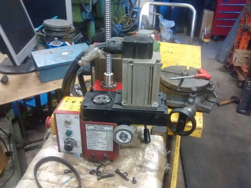
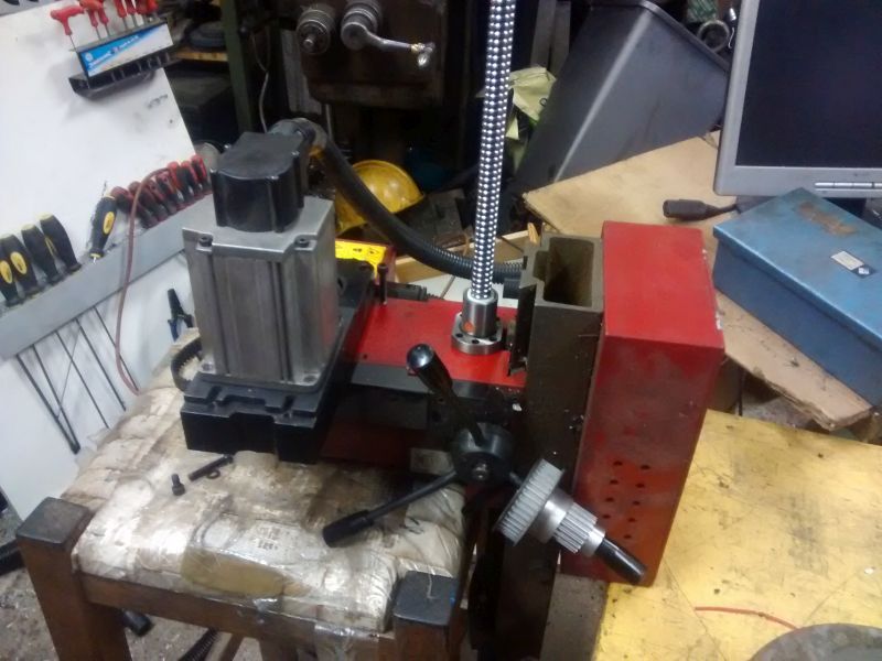
If you remove the four screws holding the main motor and spindle block (plastic) and the motor will then swing 90 degs to the side. So having seen this done, it will allow masses of room to get the ball nut mounted behind it in the centre. The motor will require an L bracket underneath it for support, and while I am doing mine, I will up the gear ratio to give me another 50% in speed. 100% has been tried before, but it did lose a fair amount of power, but I think things should be ok at a 50% uprate as long as I don't go using big cutters.
Here are a couple of pictures to show what I mean. The coarse handle downfeed and the fine feed will both be removed as they are not required.

Motor swung to one side.

Z%20conversion1_zpsuoo45odv.jpg


Where the ball nut will be fitted, the screw will go downwards, so not sticking up in the air.

Z%20conversion2_zpsbxotwhf6.jpg


John
 
Last edited:
Just to add a little to the above where I am considering uprating the speed.
I don't know if doing that will blow the normal circuit board, which I suspect it might. On the version of mill I have bought, Arc had the circuit board modified so that it shouldn't blow even if the quill came to a dead stop whilst in operation, it just shuts down, and as long as a power off / on is done, it should start up as normal. I suppose the special SX2 from LMS should have the same thing, as Arc share their findings with them, that is where the strengthened column comes from.
I will be doing a full post on making this machine, but it is now being held up by good quality parts from China which won't be here for at least another month, but I can give you a bit of insight into what has been bought from China, to give you some idea of the cost. I am hoping to make the complete machine and everything that goes with it for less than £1750. I have just bought a second hand 15" touch screen monitor off ebay for less than £80, and it is bomb proof, it could be kicked around the workshop floor and still display Mach 3, plus another litle gadget, a pendant controller for 4 axis Mach 3 was only just over £20. So things are moving slowly but surely, just how I like it.

Ball screws

http://www.ebay.co.uk/itm/160577603846

Stepper controllers

http://www.ebay.co.uk/itm/NEMA23-Stepper-Motor-CNC-Driver-2M542-Controller-/140749152634

Breakout board

http://www.ebay.co.uk/itm/261395836087?_trksid=p2059210.m2749.l2649&ssPageName=STRK%3AMEBIDX%3AIT

Everything else is being sourced locally.

John
 
Ahhhh interesting.
It is even easier on the old original X2's (like mine) as there is enough room to fit the ball nut without moving the motor.
Looking forward to seeing more.
 
I found it has been done before, tho with the original version.
Note the gap between motor mount and column, room galore.

X2-YZ-300.jpg
 
Simon,
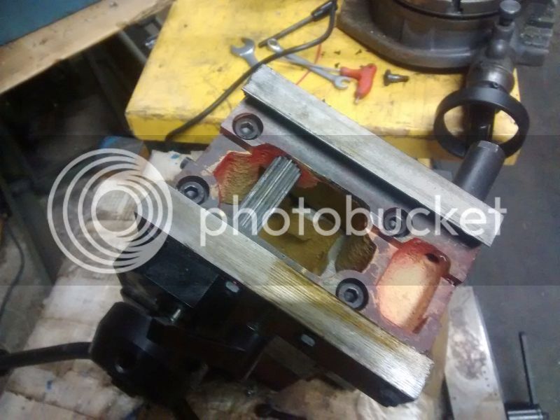
We looked at it that way, but the size of ballscrew we want to use (a very strong 16mm) the nut just wouldn't fit in without hacking off almost all of it's support flange. That looks to be a much smaller screw.
Plus doing it in that position means you have to cut through all sorts of casting shapes. By taking it further forwards, you come into well supported and easy to machine areas.

Z%20conversion3_zps79tjhja6.jpg


Just our way of doing things, make it bombproof from day one and it shouldn't cause any problems later.
All we are after is a very rigid setup with zero backlash, and of course, no crabbing.

John
 
Last edited:
I am now resurrecting this post as things have started to happen.

If you haven't read from the beginning, we wanted to mount up a 16mm ballscrew through the head, to stop the 'crabbing' that is liable to happen if the ballscrew mod was to hang it on the side. The other concern, and why we have gone for the stronger 16mm ballscrew rather than the normal 12mm ones, which allows you to mount them in the centre without too much trouble, but we didn't want the ball nut driving the screw, we need to do it the other way, so avoiding having the screw sticking up in the air.
My mate, John S, has done most of the physical development work, with small inputs from myself. John has already started on his build, I will be following along a little later when my new 12ft x 8ft metal sub workshop has been erected and placed in position.
Just to point out, there will be a few oddities shown on these builds because everything has been taken into account, like having the z axis ballscrew mounted off centre to account for the weight of the motor hanging off the side in a new position. All this calculation should produce a very stable machine compared to what others have been offering, which as far as I am concerned are just lash ups to get a machine to work for the cheapest price. This build is to get you the optimum mechanics with a little more machine work than is normally done. I will be doing just a couple of things differently to John S. as I will be mounting other things on the head, but basically, other than that, they will be the same.

So anyway, John S has started his build, and until I start mine, you can follow his along on there, even now it is an eye opener as like myself, he tries to throw in a bit of humour as well.

http://www.model-engineer.co.uk/forums/postings.asp?th=119335&p=1


John
 
Back
Top