Brian,
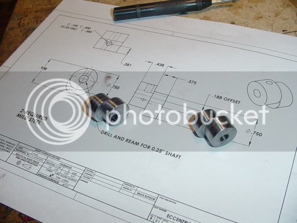
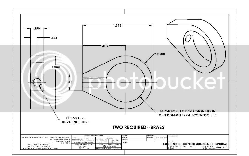
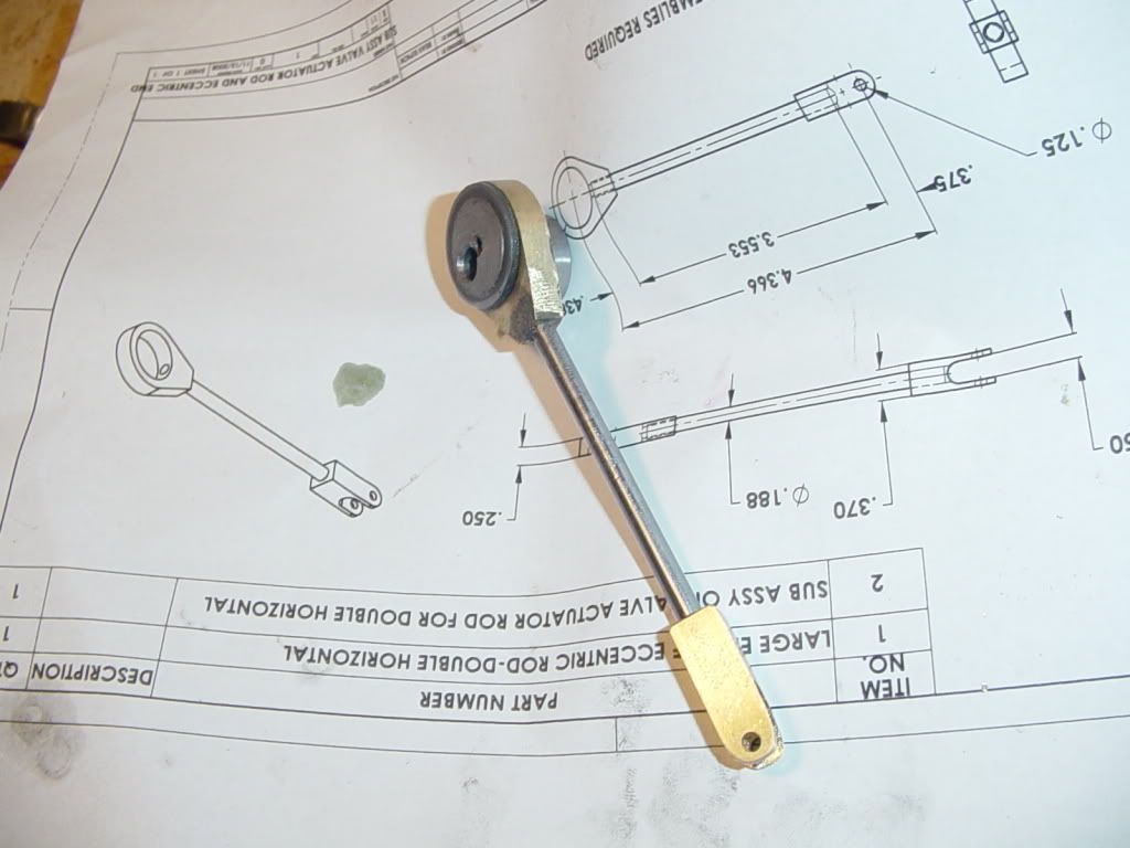
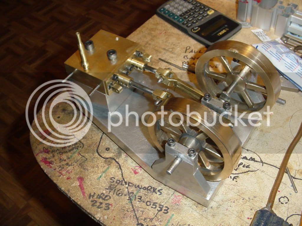
Does Solidworks compute the angle of the tangents for the eccentric strap? That is, the angle the sides of the large end and make with the centerline? For machining these using a rotab that would be useful to know on the plans.
I did some math/trig calc. and got 26.255 degrees.
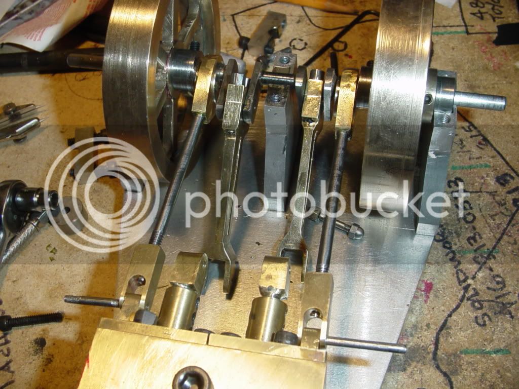
I noticed that this part is a duplicate of that on the double scale beam engine, and I will be making this part soon.


 ) on my current build.