Horizontal Air Cooled Engine

Home Model Engine Machinist Forum

Help Support Home Model Engine Machinist Forum:

This site may earn a commission from merchant affiliate links, including eBay, Amazon, and others.
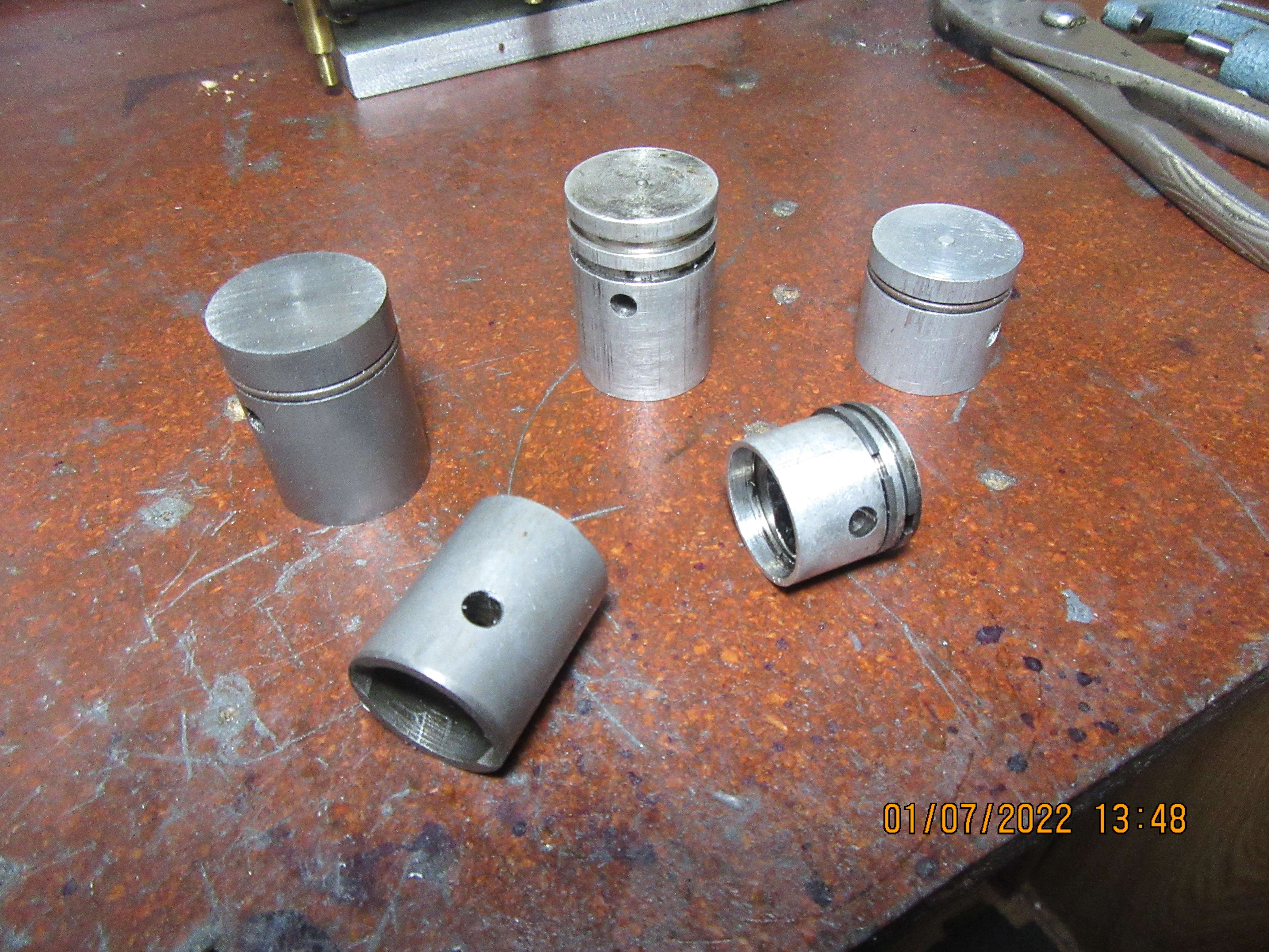
Today I'm just piddling around putting in time. I had to look thru all my various bins of junk to find something, and what I actually found was a plethora of pistons. I see two with Viton rings, one with cast iron rings, one with no rings, and one that had been lapped into a cylinder without even any ring grooves. I have no idea why I saved these, nor what was wrong with them. I guess it's part of the "Never throw anything out" syndrome that I have. I'll keep them. Most of them have a thick enough wall that I could perhaps use them in an engine with a 31/32" bore some day.
ZhdewW.jpg
 
Brian, if you are looking for a project may i humbly suggest the brass stirling 60 done in Rupnows imperialized version. not that i am looking for redrawn plans in imperial sizes for it or anything wink wink. :)

but seriously the piston with 2 rings on it already install sort of looks like the webster piston?
 
werowance--No, I won't be building that engine. It looks very nice, but it's not my kind of thing. I have built one Sterling engine a few years ago, and it works great. I will try to find a link to it.--Brian
CJivz4.jpg
 
Last edited:
I'm not finished with this engine yet. I'm waiting for a length of the right kind of iron for making rings to arrive here from Wisconsin. In the meanwhile I've been tidying up my shop, putting away tools, and changing a stripped nylon gear on my milling machine and adding a lever/lock I designed to my mill to keep it from jumping out of low gear. ---And, having my first experience with annular cutters. After a bit of confusion on my side (ordered three of the wrong R8 holders, returned them and bought one of the correct holders for the annular cutters) I am most impressed with the way these annular cutters work.
 
Today I went digging thru my stock of brass, and found a length of 1.25" diameter brass. This will be big enough to make a 7/8" external lap from. I may make a new piston from cast iron, and lap it to be a very precision fit into the cylinder bore. This will definitely help with the compression issues. I will still make new cast iron rings for the piston, when my length of cast iron specifically for making rings from arrives here from Wisconsin. Right now my aluminum piston has about 0.002" diametral clearance in the cylinder. I should be able to bring that down to 0.0002" diametral clearance with the lap and a cast iron piston.
oY9RVn.jpg
 
So---this is the external lap for a 7/8" piston. It is drilled and reamed to 0.875" thru. I've stuck a 7/8" piston into one end of it for "show and tell". In actual use, there are no rings installed on the piston. The sawcut lets it open to greater than 0.875", and lets it close to less than 0.0875". The single shcs in the center provides the clamping force to close it. In use, the piston is mounted on an arbor of lesser diameter that fits into the counterbore in the piston and cross-pinned thru the piston pin bore, and is held in the lathe chuck. The brass lap is coated with 600 grit lapping paste on the inside and held in your hand, and is worked back and forth on the rotating piston at about 70 rpm. You start with a slightly oversize piston and work it with the lap until it will just fit (somewhat tightly) into the cylinder. then everything is disassembled and brushed with dishsoap and an old toothbrush to clean away any remaining lapping paste. You have to be ready to quickly let go of the lap if it "grabs". Don't want your arm wound up in the lathe!!! If it does "grab", you let it go, shut off the lathe, and then walk everything out to your bench press, press the piston out, then back into your lathe to finish it up.
kl7IeN.jpg
 
When I made this external lap, I reamed it with a 0.875" reamer. After I put in the saw cut, it closed up a bit due to internal stresses in the brass and reads about 0.870". Next step will be to coat a piece of 7/8" round cold rolled in my lathe, add some lapping compound to it, and lap to an even 0.875" inside diameter. At that point I will tighten the cross bolt and close the sawcut up a bit more, and again lap it on the 7/8" diameter rod until I reach a point where the i.d. is 0.880" inside diameter when the clamp screw is backed off. This way I can make my piston .002" to 0.003" oversize, then using my external lap and lapping paste bring the piston down to an exact 0.875" diameter for a snug fit inside the cylinder.
 
Why do you want to lap the piston? Compression is dependent on the rings, not the piston. Unless you are trying to run without rings the size of the piston, within reason is not important. Unless you have a perfectly lapped piston and a perfectly lapped cylinder compression is determined by the rings.
 
Gordon--I have an aluminum piston with cast iron rings, and the piston is 0.002" less in diameter than the cylinder bore. The rings are "almost good enough" but not quite. They do hold compression but not enough for the engine to fire. By reducing that .002" piston clearance down to almost nothing, there will be less room for compression to leak down past the rings. Also, by making the new piston from cast iron , same as the cylinder, I won't have the differential expansion that will make an aluminum piston "grow" inside a cast iron cylinder when heated up. Cast iron has enough free graphite in it's metallurgical make up that it will generate less wall friction than an aluminum piston.
 
Brian: You may be right but there must be some reason why in almost all cases they are using alum pistons in a CI cylinder. I would be inclined to think that the problem is with the rings, not the piston. I will be interested in seeing your results.
 
Gordon--I am pretty sure they use aluminum pistons because of the tremendous weight difference, an aluminum piston only weighs 1/3 of a cast iron piston. This great reduction in mass lets the engines rev hire and be much more responsive to the throttle .
 
I am also kind of running an experiment here. I am back to working on my Atkinson Differential engine. I can get it to run for 15 seconds and then die. I am sure that the problem is compression. Compression on this engine is marginal even if everything is done exactly right. I have made probably six attempts at making rings for this engine. I finally decided to purchase a set of rings from Otto (Dave Reed) to see if that works better. These rings are 3/32 wide instead of .040 but the thickness is about the same at .055. The gap in the rings is quite a bit wider than on the ones I made. They are quite a bit stiffer. They are going to have more drag but hopefully better sealing. I am also thinking about a heavier flywheel. The present flywheel is aluminum, and I am not sure if additional inertia wins or more power to turn it wins.

OK Enough of stealing your thread. Sorry. Back to my cave.
 
Cast iron has enough free graphite in it's metallurgical make up that it will generate less wall friction than an aluminum piston.

That lump of ductile iron you are using won't have anywhere near as much free graphite in it as the grey iron you are waiting for.
 
Hi Brian,
What if you machine some oil grooves below the piston ring groove. Small size V grooves to hold the oil on piston. Maybe it will help in reducing leakage past the piston, improving compression.

Regards
Nikhil
 
Hi Brian,
What if you machine some oil grooves below the piston ring groove. Small size V grooves to hold the oil on piston. Maybe it will help in reducing leakage past the piston, improving compression.

Regards
Nikhil
Or, make the rings the correct size?
 

Latest posts

Back
Top