Homemade DRO...maybe...sort of...

Home Model Engine Machinist Forum

Help Support Home Model Engine Machinist Forum:

This site may earn a commission from merchant affiliate links, including eBay, Amazon, and others.
That's a heck of a good price. If you can put a longer scale in it some how, would be great. My 18" scale for my lathe w/o the display was better than a $100. Nice find gentlemen. As usual a day late and $1 short.............

Matt
 
Thanks Milton.

As for the rest of you...lovely....I get to investing in something...and someone has to point out some alternatives that cause you to pause. :big: But aha! I will be able to add features and goodies!!! Like a tachometer!

When last we left our hero...he'd ordered some parts.

Went ahead and used the sockets. Trimmed some off with the Dremel (makes a difference if you use a cut off wheel instead of a grinder!). That went well.

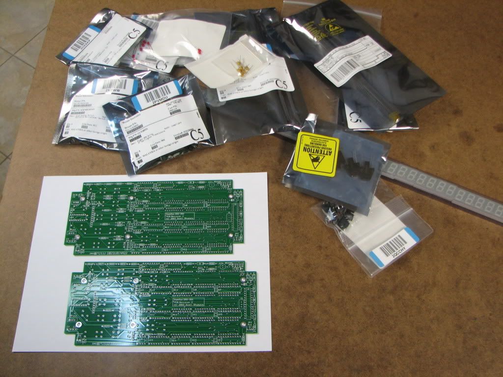
Here's the bare PCBs and packages of parts...

IMG_4532.jpg


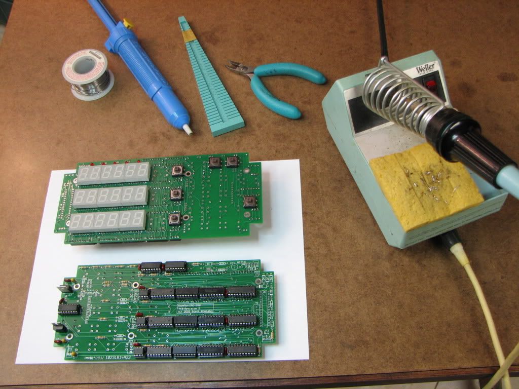
And here we have some nearly completed boards...

IMG_4533.jpg


I haven't used the soldering iron for a long long time. Ah the smell of melting solder and the occasional toasted digit. Brought back many memories...

Soldering a hole I hadn't put a part in it.
Miscounting and not soldering a hole.
Solder bridges.
Is that plus? Or minus?
Where the heck is pin 1?
Oh no...an LED...is the longer leg the cathode? Or the anode? What the heck is an anode?

Almost didn't realize that some parts go on the other side.

Now that I see it, I'll probably go ahead and spring for some of the connectors. Still have loads to do. In particular...getting a processor hooked up.

On that note...I woke up the other night realizing that my favorite processor wasn't going to do the job. I forgot how power voltages have changed over time. 5V vs 3.3V. But I think I have another processor that will do.

We leave our hero slightly perplexed.

 
Looks like you're making progress Zee !

What's the blue pyramid shaped thing next to the cutters in your pic?

Cheers

Jim

 
Looking good Zee. Be interested to see your processor solution / implementation.
 
Zee, your soldering iron, bender jig and solder sucker all take me back to my formative years. I've still got the same Weller station as the one you show here. It still works although the plug from the iron wants to keep sliding out of the socket. I'll bet you are using the PTA7 tip too, huh?

The rule used to be that all LED's had the long leg as positive (anode) and the flatted side of the body (look close) was negative (cathode) to match the flat line that gets drawn on a schematic (triangle with a tangent straight line) but then someone came out with some LED's where the long leg was negative and blew the whole convention out the window. Ah, but that was a long time ago...... I don't know where the convention stands today but I'm guessing it depends on whether they are made in China or not.
 
Rick...I think I'll try the Cypress CY8C29466. I've used it in the past and have the evaluation board for it. It turns out to have the same package outline as the PIC. I mean, it fits the 2x14 pin outline on the board! A couple of 2x7 sockets will fit end-to-end and I can easily remove the processor. A little trace cutting and wiring...and I think I'll be good. The part works from 3.3 to 5.25 and most of the pins are configurable. I shouldn't need a crystal either. 8 traces to cut and 7 of those get rewired. I can even hook up a connector and be able to program in situ if I want to or not bother with 2 of the pins. I haven't looked at the reset function yet but if I have to push a button to start it...that's no biggie.

Trout...Your memory is better than mine. I have no idea about the tip...but it came with the iron. Last night I remembered that the T1-3/4 LEDs have a flat on them. If I remember correctly that's the negative side...the little bar in the diode symbol. Of course, these little LEDs don't have a flat...but the length of the lead clues me in. Doesn't really matter...I'll temporarily install one and see if it lights up...if it doesn't...I'll try the other way.

Gee..this could open a can of worms...which way does the current flow? Seems like I remember the engineer and the technician differ on this. For the engineer, the current flowed in the direction of the diode's symbol (arrow) but the technician would say it flows the other way. And what about them holes? If the electron is moving right...then the hole is moving left. It's been a long time. :big: Well let's just leave that lie.
 
Hi, Zee

Remember the magnetic dro sensor from the beginning of the thread that I couldn't get the information from the manufacturer? I got hold of a sensor, a piece of magnetic tape and I'm going to "reverse engineer" the system. I've taken some measurements and what I found so far is that the sensor are composed of and array of hall sensors that give a 2 phase like sine wave output. A close look at the display module revealed, apart from the microprocessor, a precision quad op-amp and a double comparator so, each scale outputs to the micro 2 analog and 2 digital signals. I've copied this amplifier and when I receive the parts I've ordered, I'm going to mount the sensor and strip on the micro mill's table and figure out the signals.
 
Just a quickie post...

Found another pin I missed soldering...either eyesight or I can't count anymore (which might help Dean with the M&Ms).

Also...found I'd put a switch in the wrong place. I could remap it but decided to desolder and move it. Always a risk of lifting a pad...but I was lucky ;D.

Slow progress...mainly disappointed that I haven't been able to keep up with everyones' threads.

Been doing a little programming too...but also slow. Work is starting to eat up hours and since I program at work...I'm somewhat burned out.
 
Hi Zee, another of my many hobbies is electronics.

No IC's just plain good ole discrete transistor circuits.

Now a days, the cathode being the negative side of the diode is the shorter lead on a LED.
Also they have a flat on the lens to denote neg. term.

Just like the electrolytic capacitors have the neg. side shorter lead.

Electron current from neg. to pos. But your just pulling our leg on that one. :big:

Conventional current from more positive potential to lesser positive.

NPN = collector more positive than base, reversed biased, and base more positive than emitter, forward biased. silicon transitor

PNP the exact opposite...

Vbe = 0.6 - 0.7v.

I'm just getting carried away, having fun with this post.

Any way just thought I would throw this in here for fun...

Looks like yur board is coming a long nice.
You;ll have it up and running in no time... ;)

 
Hobby,

Glad your having fun :bow:

I didn't understand a word of it; but that's not at all suprising. :-\

Best Regards
Bob
 
yeh, I know what ya mean.

I think the only part that makes any sense is when I wrote, " HI Zee",

after that it all becomes a bunch of jarble... Rof}


zeeprogrammer said:
Just a quickie post...

Found another pin I missed soldering...either eyesight or I can't count anymore (which might help Dean with the M&Ms).

Wha... huh? Did I hear my name mentioned along side the magic candies?

I dunno anything about what's going on in this thread. "I know nothing... nothing" when it comes to all that 'lektronikal jibber-jabber, so I'm just looking at all the pretty pictures and listening for the mention of the sacred ovoid.

Good luck, Zee.

Dean

 
hobby said:
Electron current from neg. to pos. But your just pulling our leg on that one.

Ha! Cheater..you got specific with the 'electron'. You're quite right, 'electron current' flows from neg to pos. But that's not how I was taught...I was taught 'current' flows from pos to neg. I was taught the 'hole' approach. :big:

Maryak said:
Glad your having fun

Fun? Not really. It's made me remember why I wanted a hobby significantly different from my day job. Building the DRO is on my list of "I'll never do that again"...along with plastering wallboard and drinking rum.

I want this done so I can get back to machining and responding to everybody's threads.

Yeah...just finished soldering 8 wires to the wrong pins. Phoo.
 
Yeh but remember, the whole approach to the ,"hole approach" has to do with semiconductors only, once you get away from them thingies, the holes just don't add up anymore.

But pos. to neg. (conventional current flow, is the best way to understand signal generation, and amplification), I think the only time I use the cheating (electron) method is when I'm playing with the PNP transistors, and bias resistors.

But other than that conventional current (pos to neg.) rules... :D

--------
"Building the DRO is on my list of "I'll never do that again"
-----------
I guess that means your not going to go into business building these and selling them to the rest of us in this group. :big:
--------------------

Looking forward to seeing your board in action...

Really I need to get back to my projects, I'm getting pulled away reading all these great posts, from these superb craftsman, with exceptional craftsmanship...

This is the freindliest forum out there.
Everybody is really nice, and helpful,
in answering replies, unlike some other forums out there.


Zee, while you're sidelined there for awhile I thought I would throw this into the mix albeit a little off topic:

Many people think that electricity is electrons flowing at the speed of light but electrons actually flow quite slowly, at speeds on the order of centimeters per minute. And in AC circuits the electrons don't really flow at all, instead they sit in place and vibrate. It's the energy in the circuit which flows fast, not the electrons.

Metals are always full of movable electrons. In a simple circuit, all of the wires are totally packed full of electrons all the time. And when a battery or generator pumps the electrons at one point in the circuit, electrons in the entire loop of the circuit are forced to flow, and energy spreads almost instantly throughout the entire circuit. This happens even though the electrons move very slowly.

To aid your understanding, imagine a large wheel. If you give it a spin, the entire wheel moves as a unit, and this is how you transmit mechanical energy almost instantly to all parts of the wheel's rim. But notice that the wheel itself didn't move very fast. The material of the wheel is like the electrons in a wire. Electrical energy is like the "jerk", the mechanical energy wave which you sent to all parts of the wheel when you gave it a spin. Mechanical energy moves incredibly quickly to all parts of the wheel, but the wheel's atoms didn't have to travel rapidly in order for this to happen.

-Trout

 
Another way to think about it is to imagine the wire as a hose filled with tightly packed BBs (the electrons). If I push more BBs into one end of the hose, BBs will fall out of the other end at the same rate as they are pushed in. All the BBs move, but not nearly as fast as the input BBs *appear* to arrive at the output end of the hose.
 

Latest posts

Back
Top