-(Help)- Flame Licker Timing

Home Model Engine Machinist Forum

Help Support Home Model Engine Machinist Forum:

This site may earn a commission from merchant affiliate links, including eBay, Amazon, and others.

allen56am

Member
Joined
Dec 3, 2016
Messages
15
Reaction score
0
Hi Frends, I am (Trying ) to build my very first engine, Its a Flame Licker, I am at the point where I am ready to make the cam, I need to know ( All About) the slide valve timing, (To Let The Flame in) When it should start to open and close and anything else you think I may need to know, It seems like I saw some place that the the slide valve should open 20 degrees before the piston is at TDC, I don't know if that is true or not ? And I have no idea when ( What degree the slide valve should close) I just need to where to start ? So I can make a cam.
Thank You All.

15420875_10211708715664326_535180868733732385_n (1).jpg


15442168_10211708710304192_7804079570316105620_n.jpg


15492409_10211708710424195_399272569242951907_n (1).jpg


15492443_10211708707504122_1734824247894612610_n.jpg
 
Sorry about my ugly engine, After seeing all the beautiful engines on here I am totally embarrassed, But this is a learning experience for me (First Engine) I am having fun and learning through, The next one I will be starting from scratch with all new materials :wall:
 
Fine tuning of the valve operation of a flame licker is one of the ways to get them to run/run better so whatever you do needs to be adjustable. Ideally, you want the valve closed for as long as there is any significant vacuum (power) to be had, then opened immediately to prevent compression. A thin valve material (such as shim stock or feeler gauge) may be able to release compression if it starts to occur, independent of the timing, depending on design. Jan Ridders' internal valve flame lickers use this principal.
 
Ok, That all sounds like really good information, I especially like the part about preventing compression, That makes sense to me, I hadn't thought about that.
Thank you for your time and help, I really appreciate it.
 
It seems like the Germans are way ahead of us in flamelicker design. If you look at most of their engines they have a pressure release valve that operates under gravity just as the engine is coming to TDC. This eliminates our usual problem of compression pressure being released through the flame hole and blowing the flame out.

Anyway back to your cam.

On my Scott engine, the cam starts to operate at exactly BDC and closes at TDC.
They are nothing special to make, just opening and closing on a 180 degree split.
Sorry about not having a better picture but the lower bit is the cam in the marking out stage.

SCOTT120.jpg


Doing the cut

SCOTT122.jpg


Finished milling, just need to round over the transition a little with a file

SCOTT123.jpg


Cam and crank finished

SCOTT128.jpg


With a little geometry you should be able to work out the diameter of the cam to give you the correct amount of movement required by your sliding valve.

As I stated earlier this week, I used a graphite block for my valve but it could just as easily have been a sliding plate.

SCOTT172.jpg


I hope this helps a little.

I wouldn't expect you to replicate what I did, but by seeing how other people do things can give you ideas of how to tackle your own problems.


John
 
Mr. Blogwitch, I love the idea of the compression release (Ball Valve) on the top of the cylinder head, I am definitely going to do that, I didnt have a good education and I didnt get to go to a college or anything like that, So geometry is impossible for me, I will just try to make a cam that looks like yours from your picture, I will probably make (Them) from 1/4 plywood wood in different sizes until I can get one to have the valve open & closed at the correct time, I will also try to build adjustment into everything I can the has anything to do with the flame port timing, I wish there was some way that I would have some idea of what size diameter cam to start with, That woud be great, But I have no idea, Also I have scraped the idea of using the stainless steel slide valve I made, I feel like it is extremely heavy and is also wider than it needs to be adding more weight and drag, I have ordered a graphite block to work with,By the way, Your work looks amazing, Thank you so much for taking the time to help me, I really do appreciate very much, It really means a lot to me.
 
Mr. Fcheslop, I did go to the Jan Ridders & John Tom websites, They are both just full of beautiful engine's and tons of great information, Thank you so much for taking the time to help me.
 
Allen,

What you have to remember is that I am working from plans and castings, so hopefully all dimensions and working out have been done for me. So don't go putting yourself down because of lack of certain types of education, I am sure that there are many people such as yourself on here who dread it when formulae and working out are quoted. I am one of those at certain levels, but manage to muddle through by asking the right type of questions when required, everyone cannot know everything, that is why we try to help each other.

Now, the unfortunate bit, in your case, certain dimensions have to be worked out, but if working with pencil, paper and ruler, you can usually get close enough by drawing a neat diagram and taking measurements, even having to rub out and try again until you get it right.
You would work backwards, from knowing how much of a flame slot you have to cover, plus a little bit, then how far your cam should be away from the flame slot cover and then where you put in a pivot point you can draw and work things out to close enough.
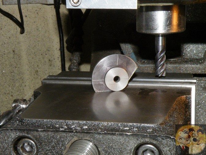
The shape of the cam should be basically as I have shown, just a different 'lift' to make sure, the small diameter is when the flame hole is totally uncovered (on the suck in stroke of the piston) and the larger diameter when the piston is on the vacuum (flame port closed) stroke.

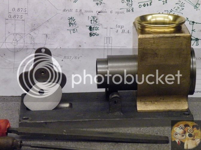
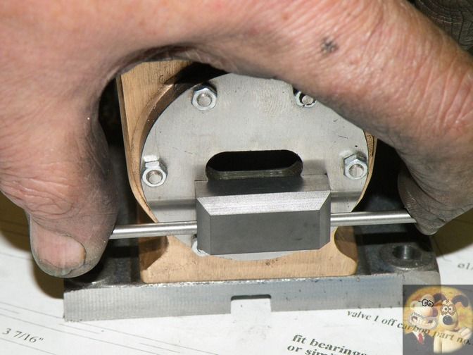
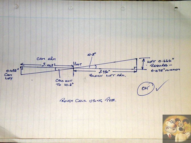
Just to prove that I don't tell lies, here is the proving sketch I did for the Scott engine above, so that I could have the graphite block being lifted up instead of dropping to let the flame in as suggested by the plans and still using the cam I had already made.

SCOTT210.jpg


Done with paper, pen and ruler and only a tiny bit of basic working out with a calculator or a little desktop engineering calculations program, and I am sure that if you can get the dimensions, someone will step in and work things out for you.

I do hope this doesn't confuse you any further.

John
 

Latest posts

Back
Top