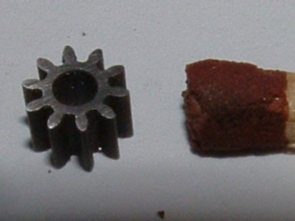
Wire Cut EDM is also my weapon of choice for small gears.
This is a 10T x 64 DP gear (used for Slotcar racing).
When wire cutting the external gear the wire cut MUST start in the middle of a tooth crest as the end leaves an unavoidable "spike" that must be removed - if this is on a tooth flank the gear is useless.
Using EDM you can also cut from pre-hardened and tempered stock.
Also for small numbers of teeth you can moderate the tooth profiles by generating them on Autocad - to eliminate the interference problems.
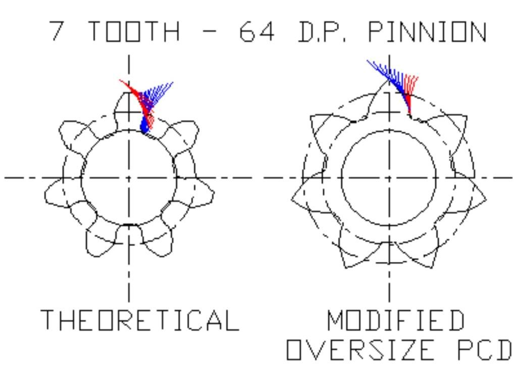
You can also do non-standard gears such as this 7T 64 DP below.
The profile to the left is a theoretical "Rack-Cut" involute profile - note the severe undercutting in the dedendum and the root diameter is too small in any case (had to run on a 2 dia shaft) - so I generated the profile for an oversize PCD using the 38T gear profile as the "generator".
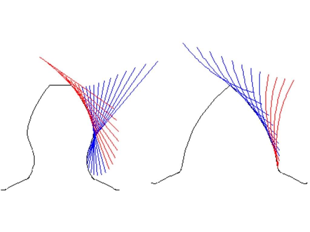
The illustration above shows the generation steps in a CAD drawing (the hard way).
Once you have developed your profile you go directly via dwg, dxf Solid Edge etc direct to your wire cut machine.
I generally don't approve of non-standard gearing but with small numbers of teeth or through dint of circumstance its sometimes the only thing you can do.
Regards,
Ken
View attachment Dump.dwg


")