Gears...

Home Model Engine Machinist Forum

Help Support Home Model Engine Machinist Forum:

This site may earn a commission from merchant affiliate links, including eBay, Amazon, and others.
Pete,
I have read a few of your posts on HSM and it is very clear that you know a considerable amount about gears and EDM.

My question is simple can EDM be used to make a bevel gear?

Dan
 
Dan,
Take a look at this out of interest.

[ame]http://www.youtube.com/watch?v=RV8Dq6mslnE[/ame]

John S.
 
JohnS,
Very interesting. Was that done with a solid model and a ball end mill with a 3 axis cnc machine?

I have Mach3 and can draw what I need as a solid model. What did you use for CAM?

Dan
 
Yes, solid model off the web, I thought it was the SPI site but can't find the model I used again.

Saved as an STL file, opened up in Vectric's Cut3D program, roughed out with 6mm ball nose and finished in two passes at 90 degrees to one another with 2mm ball nose.

The video is actually on the finish pass, that why it doesn't look to be cutting, never thought to video it on the initial path.

Just standard CNC bench mill on 3 axis, the chuck is just work holding bolted to the bed.

Took about an hour but the stepover was quite course, I just wanted to prove the concept instead of spending 4 or 5 hours with a small step over only to find it didn't work.

John S
 
Found some gears on the Rush Gear site, [ no spiral bevels thought ]
Took a normal bevel and ran it thru Cut3D and got this.

bevel1.jpg


John S.
 
Cool stuff. I'd think there's a limit or relationship to to how small a CNC cutter has to be and the DP of the gear to be produced by it. Say a 1/16" or 1mm cutter. What gears and/or DP's could that generate reasonably? It seems like the limit would be the space in the 'notch' of a gear (I've not got the proper name for the bit-the-tooth-goes-into handy)


shred said:
I'd think there's a limit or relationship to to how small a CNC cutter has to be and the DP of the gear to be produced by it.

The DP sets the size of the cutter for spur gears, and there is a reasonably priced cad/cam solution called Involute written by Graham Baxter.

It is a bit more complicated with a bevel gear because the DP describes the big end of the gear. The face length of the gear is what sets the small end which is what is needed for cutter diameter.

The reason I am making my own gears not using commercial ones is the face length of the bevel gears for a Shay locomotive are longer then current gear practice.

John S, thanks for that screen shot that is one of the programs I have been considering.

Dan
 
Dan Rowe said:
Pete,
I have read a few of your posts on HSM and it is very clear that you know a considerable amount about gears and EDM.

My question is simple can EDM be used to make a bevel gear?

Dan
As to your question yes, Wire EDMs can be used to create bevel gears, dependent on the size and distance of the taper, with abit ingenuity I've even cut helical gears on a wire EDM. The main things to consider when having any gear wire cut is the cost, a gear can take minutes or hours dependent on the thickness of the part,accuracy and surface finish.
 
Dan Rowe said:
My question is simple can EDM be used to make a bevel gear?

Dan

Dan,

A straight bevel should be possible, yes. I have never cut one, however I have made a gear shaper cutter before -- a generating cutter like used in a Fellows gear shaper (actually just cut a section of one to prove the concept).

In a simple sense: if each "end" of a profile can be defined, then it can be wire cut. Needless to say, a bevel gear would require the blank to mounted at an inclined angle on a dividing head in the wire machine, but that's not an issue -- I have a 3R dividing head that I can mount at any angle in the machine.

PM
 
precisionmetal said:
More gears...

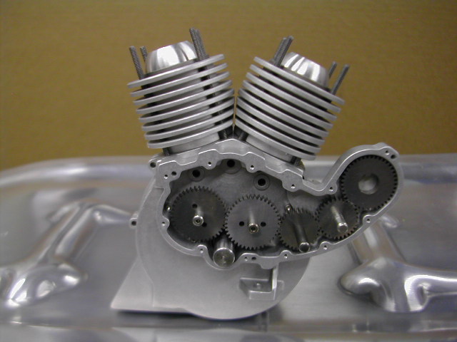
Cut these for a buddy who is working on a ¼-scale engine project. Crank gear (the small one), 2 cam gears, 2 idler gears and 1 magneto gear. The two 1/16" holes in the cam gears are for driving the cam (only one hole will be used). He wasn't sure yet whether he wanted the drive hole on a tooth, or on a gullet, so I put in one of each. Those gears have 40 teeth, so the drive holes are 175.5° apart. The crank gear has a .250" bore with a 1/16" key. Since it wasn't possible to put a keyway in the gear, I just integrated the key into the part.

Gears are 64DP 20°, with the tooth thickness reduced about .0007" from standard in order to give each "pair" about .0015" total backlash. Material is A-2, heat treated to 55Rc.

quarter-scale.jpg


Greetings All,
This is my first time posting on the board. Here are some shots of the model that I am working on. I have to say
without Pete I would not be able to build this exactly to scale. He is a good friend and craftsman. I am starting with the running engine and gearbox. Then the rest of the bike. I have the basic short block finished. I am working on the heads this week. Hopefully I will have the models done tomorrow and in the machine this weekend. I need to make the cam followers (more work from Pete) and the valve gearing will be finished. Then carb and ignition.
I hope you all enjoy. I will keep you posted.
Thanks again Pete.

wfifairing.JPG


The real deal in Morro Bay Ca.

wfiside.JPG


Without the fairing.

fullandquarter.jpg


The model engine. Notice the gears.

quarteronfull.jpg


More of the model on the full size bike.


Help with DP (Diametral Pitch)?

Browsing catalogs on involute gears I see the sizes are quoted in dp and module, how does someone starting out decide what cutters to purchase?

I imagine many parameters have to be taken into acount such as diameter, material, torque just to name a few.

A higher dp I imagine allows for better accuracy but lower torque, these are only my thoughts.

Can someone enlighten me on this subject? Is there any articles, post dvd books that you can recommend?

Thanks In Advance
Andrew
 
Andrew,
Gears are math in metal. To understand things like DP, module and circular pitch you need the formulas. These can be found in most catalogs. The download section has a good gear book that was uploaded by Steamer which is a good place to start the study of gears.

Module is a metric gear and DP is imperial. The circular pitch can be expressed metric or inch.

Dan
 
Thanks For The Information Provided So Far.

I question I am asking is how does one decide what DP cutter to purchase.

For example say I want a 2:1 reduction gear, the larger blank being 4 inch OD.

Diametral Pitch = (Teeth + 2) ÷ Outside Diameter

6 = (22 + 2) / 4
6 = (11 + 2) / 2.166


11 = (42 + 2) / 4
11 = (21 + 2) / 2.090


16 = (62 + 2) / 4
16 = (31 + 2) / 2.0625


24 = (94 + 2) / 4
24 = (47 + 2) / 2.0416

How does one decide whether to cut your gears with a 6, 11, 16, 24 DP cutter for example?

I imagine there are many parameters that have to be taken into account?
i.e.
Material: Nylon, Aluminium, Mild Steel
Power: 0.1 KW, 100 KW, 1000 KW
RPM: 1 rpm, 100 rpm, 1000 rpm, 10,000 rpm
Application: swiss watch, chaff cutter

What are the advantages of using 6 DP over a 24 DP cutter, visa versa.

Thanks in advance

 
This is a very non-scientific answer and it is aimed at model engine construction since this is a model engine group. I pick DP and buy cutters by "what looks about" right with respect to engine scale. My engines are between 0.75 inch and 1.312 dia bore. I have 32 DP cutters and 48 DP cutters. Gear loading is very light. These small teeth look right and run fine.

If you are designing gearing to transmitt significant power then my method is of little value.

I don't mean to discourage you from studying the technical details of sizing gears. I just wanted to give you the approach that I suppose a lot of model builders use in our lightly loaded applications.

Regards,

Chuck Kuhn
 
In the case of the 1/4-scale Indian engine mentioned earlier in this thread, the gears were simply "scaled" from the originals.

Andrew, unfortunately you ask some questions that can not be easily answered. There are so many variables in gear design that the subject could go on forever. Chuck's answer, along with a ... "use what's available to you" is probably a place to begin.

If you required a precise ratio of 2/1, you will undoubtedly find it easier to achieve with a higher DP, however if you need to transmit a lot of power, a numerically lower DP would be desirable.

PM

 
Andrew Stewart said:
The question I am asking is how does one decide what DP cutter to purchase.

To add to the other excellent replies; you need to consider the number of teeth in the smaller gear in the set.

Your example shows that for a 6DP gear, the small gear would have 11 teeth: this is too small to cut with a conventional cutter (12 is usually the smallest you'd go).

Big teeth on a small blank also limit the size of shaft that can go through the middle.

Cutters aren't generally available in odd-numbered DP, hence 11DP is unusual; in the module system, they generally move by increments of 0.25.

Finally, it's more conventional to work with the pitch diameter rather than the blank diameter as this makes determining the centre distance of the pair considerably more intuitive.
 
Just a question about buying "involute" or "hob" gear cutters.

I see specifications for:

1. Class "AA" "A" "B" Ground profile & "C"
2. IS, BS, DIN and ASA

Can anyone point me to or explain what these options are when buying a gear cutter and what are the most commonly used?

Thanks in advance.
Andrew
 
Back
Top