GEA, a 3.5'' live steam narrow gauge locomotive

Home Model Engine Machinist Forum

Help Support Home Model Engine Machinist Forum:

This site may earn a commission from merchant affiliate links, including eBay, Amazon, and others.

Henk

Well-Known Member
Joined
Mar 10, 2010
Messages
92
Reaction score
57
A few months ago, I purchased the plans for a narrow gauge live steam locomotive.

I have to disappoint you - I am in no hurry. I intend to occasionally update my build status. The main use however will be that whenever I have a problem I can demonstrate what I am actually doing. Also, I have been helped here. I don't have much help to offer (hopefully that will change though), so I thought at least I can add some pictures of what I am producing.

So the "GEA" is a model that is built quite a lot here in the Netherlands. You may want to look at the movie, the first locomotive is a GEA at 1:02.
http://www.youtube.com/v/QmZu3O8Oa9A&hl=nl_NL&feature=player_embedded&version=3

The reasons for me to choose this loco are relative simplicity, it is not an exact model of a full sized loco (but very much modeled after this one : http://www.smalspoormuseum.nl/Materieel/Stoomlocs/stloc1.htm) so it is OK to deviate. Also it is a small size, so my machines should be big enough for it.

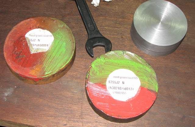
I will start off with the wheels. I get most of my raw material from the dump -recycling. It is in biking distance and I wouldn't know where else to get some of the stuff. For the wheels I found some ends of bar stock. Three lumps of various diameters (95 to 110 / wheel diameter appr. 72 mm), one of which was thick enough for two wheels. This meant that I know understand why you all love your bandsaw so much! However, for the amount of serious sawing that I need to do, I cant afford to use up the space. Anyway, being ends of barstock, it still had a material code on in, suggesting it was hot rolled steel. I have no idea whether it is relevant for the wheels yes or no so I use it. BTW, when I do finalize this project, I never expect to use it much /so I guess I should be all right.

wiel_001_small.jpg


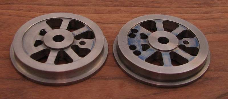
It took me quite long to get the wheel turned to looking like almost real wheels. It seems that I did find out that the ends are not the nicest parts of a bar.... I am also not realy satisfied with the surface quality of the recess, or at least where I had to blend the two directions going in, an going out. Of course I tried to make this not that visible in the photographs!
wiel_004_small.jpg


I kept the rolling surface still straight and the axle hole 1 mm smaller. I left that for after milling the spokes. My reasoning was that I want the axle hole and the rolling surface (i do not know the proper englich word, but I guess you understand) to be turned in one setup. And for that I needed the spokes. I will make up a fixture so that I can screw the wheels to a plate through the spoke holes, and then mount the plate in the 4 jaw.

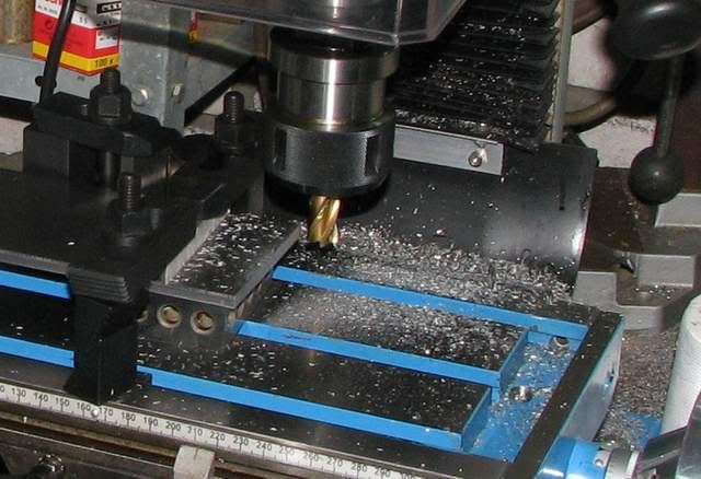
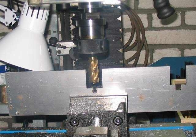
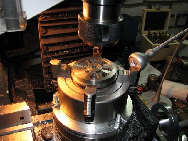
This is BTW, also the first time that I used the RT, other than making the adapter plate to hold the 4 jaw. .
wiel_009_small.jpg
.
Somewhere I hope that I would have figured out how to use the RT efficiently, but without a shadow of a doubt Bogs flywheel course helped me a lot.

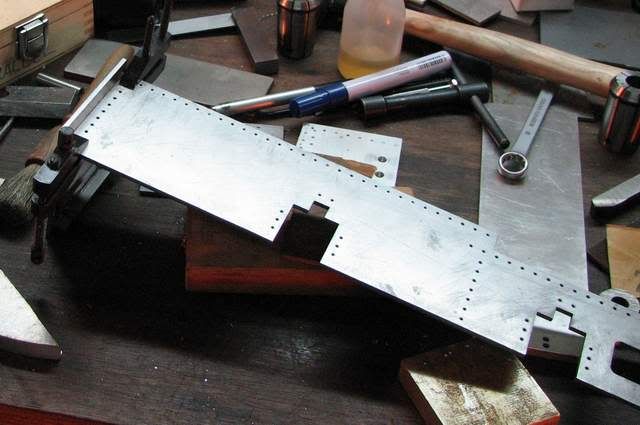
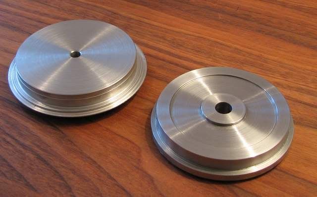
After getting it off the RT, this is what I have (three more to go).
wiel_012_small.jpg

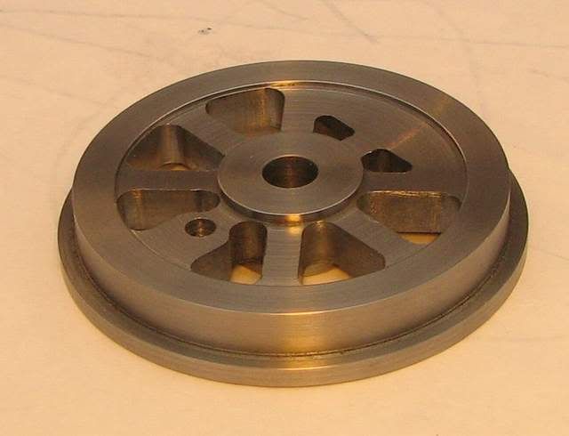
As said, it still needs accurate sizing and angle of the flange and surface.

For the very obervant: the drive pin hole (again I am open to suggestion for the regular English word!) is off by half a mm. As I kept this hole also still undersize (1 mm) I may be able to correct it. I have every intention not to remake this wheel! Also I need to try whether using the dremel to smooth the edges of the spokes results in nice looking spokes. Luckily no-one will pay close attention to the inside of the wheel, so I know where to test this.

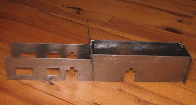
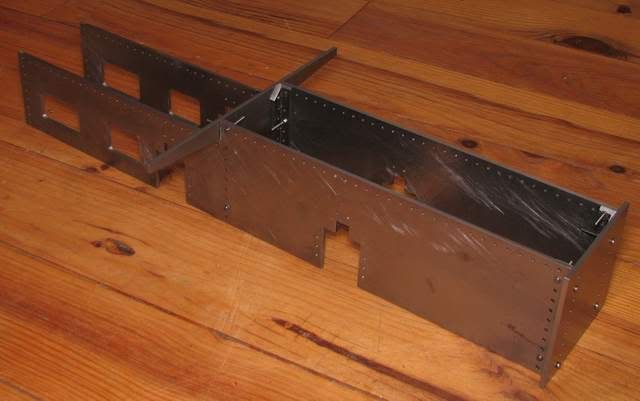
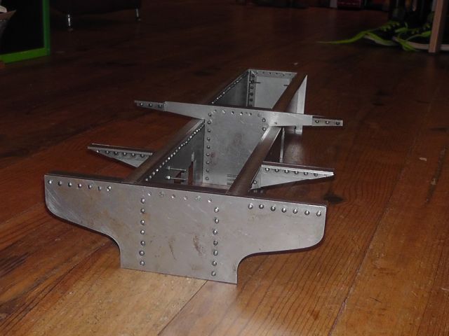
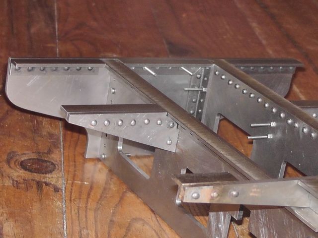
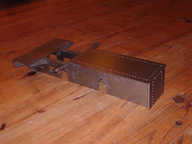
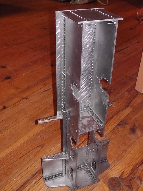
I have prodcued some parts of the frame, which I will show later on, but this is it for now.

Henk
 
The English term for that is crank pin. The offsets from the axle bore needs to be quite identical on all wheels, or else you will get binding on the drive/side rods. I can think of several fixes depending on how far off you are.

1) Bore (not drill) the proper size hole in the proper location if the bad hole is completely enclosed by the good one.

2) Bore a hole in the proper location but larger than spec. In order to enclose the wrong hole. Then turn the crank pin with one diameter for the hole and another for the rod ends.

3) Use the hole as-is and machine an eccentric crank pin.

4) Make all the other wheels the same as this one and adjust the length of the side rods to fit. This solution affects the stroke of the piston as well as possible the timing of the valve gear, but that may not be a problem if the difference is small.

The problem with using mystery metal for wheels, as I have been told, is that they will wear differently. You definitely want the wheels on each side of an axle to be made from the same material.
 
Kvom (assuming that's the way I should address you)

Thanks for taking a look and commenting / educating me on some English terms and machining.

Indeed I will start of with 1 (which should just be possible), but thee is not real issue with ending up with 2. The problem is mainly cosmetic, as I got the distance crank pin to the axle right, the hole is offcentre w.r.t. the spoke. I don't know how I managed to do that. I will do final boring probably on the lathe, as I do not have a boring bar for the mill, and preferable having each set of wheels that will be coupled together also mounted together.

On the material of the wheels: what I forgot to mention is that all wheel lumps had the same number and colorcoding on them, though the size varied. I liked this in general - at least that machining would be the same, so I did not have to learn for each wheel separately how to machine it. But indeed wheel wear is an additional bonus.

 
Given that the crank pin is attached to the side rod, it's highly unlikely that the off-center spoke would even be visible.
 
Hallo,Henk.You have already found out that material from the "lompenboer" can be hit or miss.But usually there's enough there to get rid of the rubbish content,and have a reasonable item.
Not being familiar with the material code on your steel,it sounds like it will easily take the little wear you'll put on it.
I like the spoke layout on your wheel.Normally,the "counterweight" area is completely blank,but yours with the 2 little holes looks nicely different.
Please be sure to post further progress,I for one am always interested in loco's.
 
That a great looking wheel. Since you did so well with the RT, get yourself a corner rounding cutter and follow the edges around just as you did when you milled them. The results will surpass anything a dremel can do.
 
Hans, I hadn't figured you as being of dutch origin, but still I will use mostly English, or at least my version of it.

MachineTom : Thanks. However of course I tried to photograph flatteringly. On the subject of rounding bits: First of all I haven't got one, but also I haven't figured out how then to nicely blend in from the spoke to the rim in that case. Also specifically on the hub side, I do not see how a rounding bit can come sufficiently close, so there would always be a part where I need to do filing / sanding. Putting the wheel back in the RT resulting in a not very nice angular spoke position is something I do not look forward to - but I could get over that rather easily.

On the subject of progress, wheel #2 came out rather OK (left). So probably that is why I apparently became less concentrated, leading to a minor nuisance on wheel #3 (right).
wiel_015_small.jpg

As you can see, there are a few too many holes on the counterweight area. What happened is that I drilled the holes around the crank pin hole to close together, so the width of the spoke there was 9 iso 11 mm. Luckily for me the counterweight size is sufficiently big to cover this up. So I simply swapped the crank pin position with the counterweight. I can simply plug the holes and no-one will know (not counting any of you).
 
MachineTom,

They will be run as is, after machining the taper to the rim. My impression was that it is not very common to use separate tires on model locomotive. This is mainly based on the fact that I have not seen any reference to it on the internet. Also my build manual (predating internet by almost 2 decades) assumes single wheels.

Reasons that I could think for this of are:
1) Very limited wear due to little usage anyway (not many model locomotives will run the same amount of time as the originals).
2) The load on the wheels is smaller than prototypical due to the weight being a third power (volume) and surface area a square power.
3) The tolerance in mm (or whatever your favorite unit) for a shrink fit (note: I have never tried one) for small wheels is more difficult than when the wheel is more than a meter.
4) no one will ever see the difference.

I am definitely no expert, so feel free to add / correct.
So I'd say doing separate tires makes sense when you expect a lot of wear, and / or are very concerned with being as close to the original as possible, and are willing to go to great lengths. The former I do not expect, and the latter I am not. BTW, if I see have a lot of wear, I can still turn down the wheels some more, and retrofit tires.
 
For small steel wheels such as these, there is little/no need for tires. If the center section were to be machined from aluminum or brass, then steel tires would be appropriate. As I understand it, the tread profile is important. The flange width/depth needs to be able to pass through switch frogs, the tread angle helps keep the wheels on the rails through curves, and any sharp edges need to be chamfered to avoid injuries when rerailing or carrying.
 
The reason I asked about the tires was that the wheel profile was so square. My experience with model trains showed the need for taper on the flanges, to avoid derailing on turns. This loco is just a bit larger than the 80 year old standard gauge now running around my grandsons xmas tree. There is good amount of taper on the flanges of that loco.
 
It not only looks square - it is.

Henk said:
I kept the rolling surface still straight and the axle hole 1 mm smaller. I left that for after milling the spokes.

I don't know yet how much taper I will put in. If I combine the taper on drawing with how I understand how a train behaves, the turning radius (with the flanges just touching the rail) is ~ 30 meter, less if the track is widened in the curve.

Data: 3 degrees angle on tread, diameter of center tread 72 mm, nominal track width 89 mm, and max sideways displacement of the wheels on the track of +/- 1 mm (so 87 mm width on the flanges).

My, your grandson does have a large house to boast more or less this size track inside....
 
Sounds like a great project. :) I'm looking forward to seeing more as you go.
 
Some progress, but it looks like more than I really achieved since y last post, as I did the frame plates before the wheels. The fourth wheel was milled without much to tell about it - no mayor errors.
So now I have four wheels in a shape that look like locomotive wheels, but still need the essential stuff finalized. As I do not want to rush that part, I decided to get back to the frame.

The frame size is such that it just matches with the mill travel. Or rather the other way around as I bought the mill after deciding for this project. Still I had to figure quite a bit to set it all up. Somewhere on HMEM I read that 1-2-3 blocks will be used more than you imagined : From my recent experience I can confirm that. I also did not regret buying the clamping kit.
frame_001_small.jpg

Maybe next time I would try putting the frame plate horizontal - probably a stiffer setup - but at least this worked. I sort of forgot why I did not. Probably because this was the first more or less serious milling I attempted, and I did not know how well one can clamp that way, and vertically I could use the vice.

The sides I did do sideways.
frame_003_small.jpg

I don't have a ruler this long (just measuring tape), but overall length tolerance is not that important. I did learn that the measurement tape has an error close to a mm for this length (450 mm). I guess I have the length right within a mm. BTW, the frame is 3 mm thick and feels a bit flimsy to me, so I hope that when it is all put together it is indeed sufficiently stiff.

Milling the recesses for the bearings is straightforward:
frame_005_small.jpg

The frame looks very tilted, but it is just a bad photographer not keeping the camera level.

Now in the drawing the connections between the frame plates is described as: "rivet together with 2 mm rivets and 2 mm angle iron". No actual patterns were supplied. As I wanted to keep going, I just went ahead. Now I think that I should have put more though into rivet placement on the corners. I also need to practice riveting before actually doing that.

Transferring the holes to the angle iron worked like a charm. Clamping using the machinist clamps was indeed very convenient - sure beat trying to depend on my limited tolerances to put the holes on two parts in matching positions.
frame_006_small.jpg


The full frame is now looking like this (front is on the right):
frame_008_small.jpg

frame_009_small.jpg

It is bolted with M2 screws. It will riveted rather late in the build as it needs to be taken apart quite a lot (mainly after cylinders have been positioned correctly).

Now all of a sudden it looks like something, where before it was only a bunch of plates. And I do admit to having put the wheels in the generally correct area using some pencils for axles, and feeling all warm inside. I actually may even finish this project before the end of the next decade!
 
Henk

Another loco to follow, thanks. You've made a great start

Pete
 
So finally some progress after 2 years.

I kind of stalled at the thought of doing the rivets. For some reason I wanted to be able to press them. And this would them mean making tooling to guide the anvils across a rather large distance. This put me off. Just hammering the rivets into shape also did not prove to be very satisfactory.

I remembered reading about riveting somewhere and the various anvils/mandrils/dies (any native speaker around that can confirm that the latter is the right word?) that would be needed.

So on an afternoon a few weeks ago, i just made a few of those dies. It worked relatively good. One of the things that I did do this time was to really anneal the rivets. I think that was a key step. You can see the result below. As a matter of fact I think that the picture looks better than reality. The heads are too high, and still displaced laterally-leading to irregular visual head position.
geklonken_frame_04_zps8b5658b2.jpg
 
A detailed view of some rivetson the back end:
geklonken_frame_03_zps802f405c.jpg


As you may notice, the frame is not yet fully riveted. It can still be taken apart by loosening the M2 bolts.All pieces of angle iron are riveted on one side, and the other side is bolted. Final riveting is done later in the build. But at least now I do have the confidence that I will be able to manage that when I get there.
 
This looks like a grand project and the video is wonderful. It will be fun to watch your progress over time. I wish I had tools large enough to build a project of that size.

Thayer
 
Thayer,
Actually the size of the mill and lathe was defined by wanting to make a locomotive of approximate this size. I consider them the right size for me. Bigger would eat up too much space for my liking - I still need to put bicycles in my garage.

I the mean time I made footplates.
frame_w_footplate_01_zps791c8dab.jpg

frame_w_footplate_06_zpse1e00943.jpg


Nothing spectacular, but progress happens one piece at the time. I will try to make some more shots of actual machining and set-ups, as that is what I look for in other threads / posts as well.

Btw, I can't seem to find the spellchecker anymore. Is that just me, or is that option no longer present?

Henk
 

Latest posts

Back
Top