- Joined
- Jun 24, 2010
- Messages
- 2,357
- Reaction score
- 931
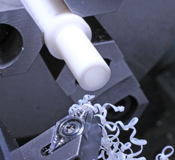
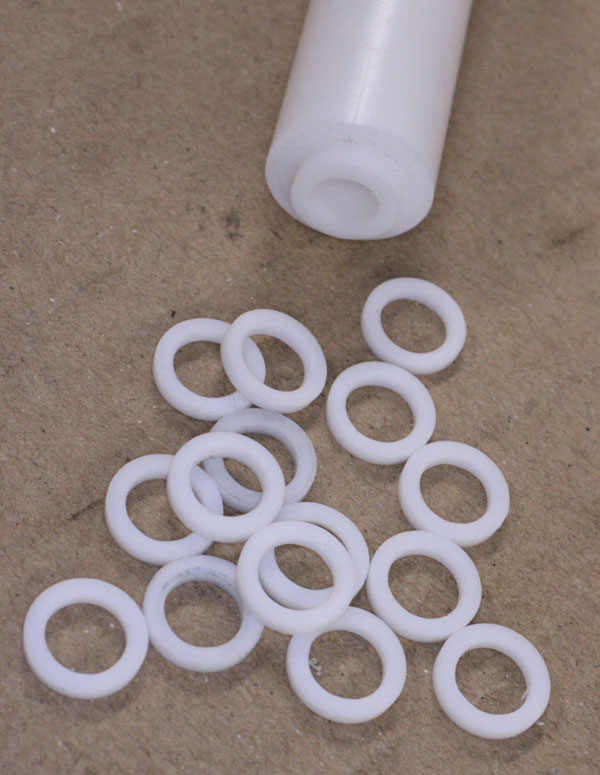
I'm making up the induction tubes for my radial. The trumpet flaring profile is coming out reasonably consistent. They need a bit of dressing but in the end have ~ 0.030" flat on the end to match the internal port counterbore face. The nut seems to engage OK. Initially after trying different sizes & hardness of O-rings, I thought I found a good combination. But after closer inspection it still seems hit & miss. The ring wants to kind of flow inside the trumpet even with hard durometer. I noticed that a dummy flat washer I made from aluminum fits very consistently, so I'm thinking the issue is more about the section shape than the durometer. I tried looking online for something that might work, but I have odd ball size, about 11mm OD x 6-7mm ID x 1-2mm thick. I don't have a lot of wiggle room washer thickness wise. Its the induction side so max temp would be the head itself. But I also need something for the exhaust side. I was thinking copper for heat & the gas seal isn't an issue like the intake side so was less concerned about that right now.
Any recommendations or ideas?
I thought about buying a stick of teflon & machining my own washers to size. But would this be soft enough to deform a bit for gas seal with typical tightening pressure? I cant get too rammy on these threads as-is but mostly I didn't want air leak messing up the mixture.