Gas Turbine build, pictorial build log.

Home Model Engine Machinist Forum

Help Support Home Model Engine Machinist Forum:

This site may earn a commission from merchant affiliate links, including eBay, Amazon, and others.
I ended up building the balancer published by the GTBA. ...This is a standalone device, no computer or software needed... Steve.

First off, what a great accomplishment on the turbine!

Re dynamic balancers, Ive looked at some web links & aside from the basic mechanics of how the shaft is spun & sensors mounted, almost all the rest is above my head! :confused:

- when you detect an imbalance, how do you then go back to the appropriate (radial) position in order to alter the mass at the right spot? Do you orient or register the shaft assembly in some manner beforehand somehow?

- how do you determine the amount of mass change to 'fix' it into balance?

- would this balancer be confined to reletively small amounts of imbalance like your turbine & teeny manufacturing differences, or could it somehow be adapted to typical combustion engines to tune crankshaft counterweight running assemblies?

- is the rpm level itself somthing that factors into correcting balance, or do you arrive at the same correction recipie by just spinning it at some safe, arbitray rotation amount?

fascinating stuff!
 
First off, what a great accomplishment on the turbine!
Thanks Peter, much appreciated.

- when you detect an imbalance, how do you then go back to the appropriate (radial) position in order to alter the mass at the right spot? Do you orient or register the shaft assembly in some manner beforehand somehow?
I will attempt to explain how this is done.

As you probably can see from the photos previously posted, the balancing rig consists of two fiberglass arms one of which has a piezo sensor attached. The electronics consists of a piezo signal amplifier with 6 sensitivity settings, a zero crossing detector, and a strobe circuit. There is also a variable DC power supply used as a speed control for the motor that spins the rotor under test. The balancer is equipped with a meter that measures the amount of imbalance detected by the sensor.

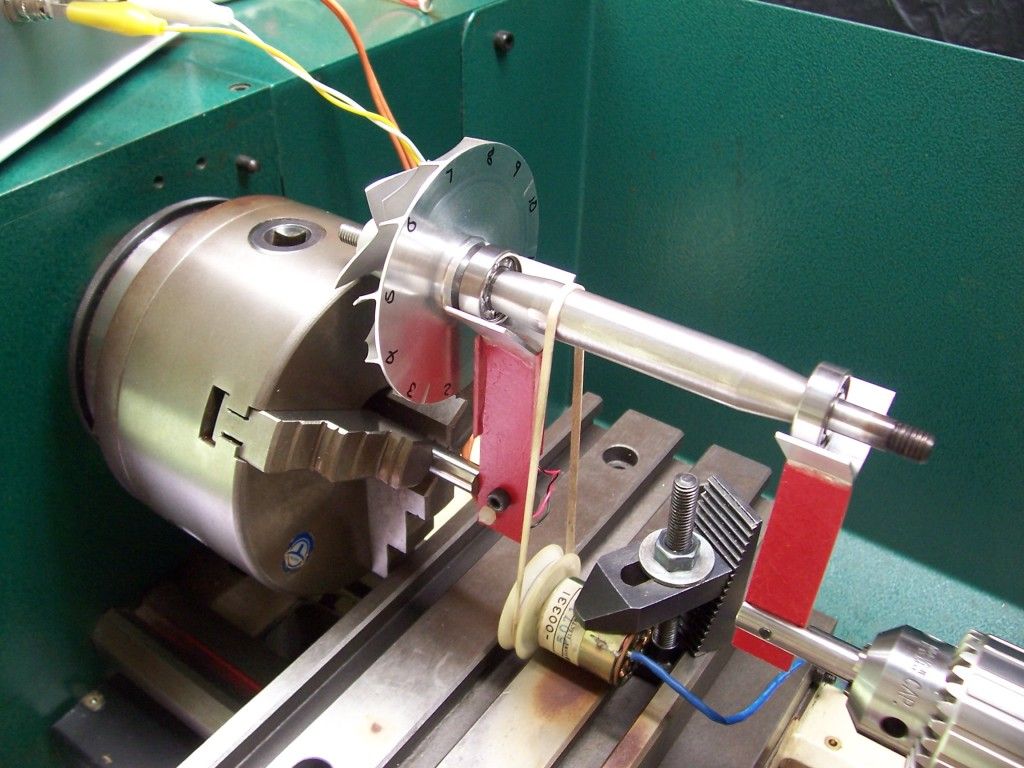
A typical balancing session session starts by spinning the rotor in the rig, increasing the speed of rotation until a resonance point is reached, the resonance point is indicated by a peaking of the signal observed on the meter and the stability of the static image of the rotor created by the strobe. The wheel to be balanced will have previously been marked at regular intervals around its circumference. Here is a photo of the compressor wheel with a set of markings.

100_1161.jpg


Once the resonance speed has been determined, the speed of the rotor is not changed for the rest of the procedure.

At this point we don't know where the imbalance point is. In order to locate it an additional weight is introduced, usually by adding a small amount of putty or plasticine to the wheel in an arbitrary location. If the position of the additional weight does not coincide with the imbalance point the static image generated by the strobe will shift either to the left or the right. The number at the top of the wheel is noted, the test weight is moved 90 degrees and the test repeated and the new number at the top of the wheel noted. This test is repeated twice more so that the test weight has been tried at 4 cardinal points around the wheel and the four resulting strobe numbers noted. These four strobe points will typically all be on one side of the wheel, the center of these strobe points will be very close to the actual imbalance in the wheel. The test weight is now placed at this center point and the strobe image shift is compared to the strobe image when the weight is removed, by moving the test weight left or right in small increments it should be possible to find a location where the strobe image no longer shifts when the weight is added or removed, this is the imbalance point.

To determine how much material to remove the test weight is moved 180 degrees from the heavy point, more putty is added (or removed) until the signal strength on the meter drops to zero. Material can now be ground off the heavy point in very small increments, and a corresponding amount of putty removed to re-balance, this is repeated till no putty remains and the wheel should theoretically be in balance. All of the above assumes that there is only one heavy point on the wheel, this is often not the case, smaller imbalance points often exist, if so, the whole procedure is repeated at a higher sensitivity setting on the piezo amplifier.

- would this balancer be confined to reletively small amounts of imbalance like your turbine & teeny manufacturing differences, or could it somehow be adapted to typical combustion engines to tune crankshaft counterweight running assemblies?
It might be possible to adapt it to crankshaft balancing, I think it would be a matter of setting the right amount of sensitivity in the amplifier and finding an appropriate resonance speed.

- is the rpm level itself somthing that factors into correcting balance, or do you arrive at the same correction recipie by just spinning it at some safe, arbitray rotation amount?
The rpm used on the balancer is determined by the natural resonance of the rotor and the sensor arms. This is the point that the rig produces the best signal for the balancer electronics.

Disclaimer !
There are probably other and better ways to balance these rotors, I'm no expert, this is just one method. ;D

Again, thanks to everyone for all the kind words and hopefully my explanations are clear enough to understand.

Regards,

Steve.
 
:idea: I would imagine that, if you connect a 2 channel oscilloscope with one channel to the piezzo amplifier and the other to reference point, you could pinpoint the unbalance location much faster. It may just be my imaginationscratch.gif
 
Oscilloscopes have been used to balance these rotors but they suffer from the same limitations as the dedicated balance detector, i.e. the signal from the piezo does not directly match the imbalance point of the rotor. The reason is the the signal generated is not just from the rotor alone, but is the resonance from the spinning rotor and the sensor arms combined, this is why the procedure outlined above is used.

Regards,

Steve.
 
Steve, this is awesome!!! Your machining is also very neat and well done. I noticed the web page that has the plans for this turbine says it is not a beginner project. Do you have suggestions for how to get started in building turbines?

If there were still karma points I would sure give you one so please accept a virtual karma point. ;) th_wav

Thank you
Pat
 
Thanks for the comments Pat, very much appreciated.

To get started there are a couple of books I'd recommend, the first is "Model Jet Engines" by Thomas Kamps, the second is "Gas Turbine Theory" by H. I. H. Saravanamuttoo, G.F.C. Rogers, H. Cohen and Paul Straznicky. Both can usually be found on Amazon, the second book is expensive, but is very detailed.

The Kamps book includes plans and instructions for an engine that these days is considered outdated, a good starter engine is the KJ-66, a forgiving and well tested design, you can find plans here. http://www.pulse-jets.com/phpbb3/viewtopic.php?f=6&t=1179

Regards,

Steve.
 
I'm new to the group and this is my first post, but I just wanted to take a second to say thanks for posting the links to the plans as well as your build pictures. I've had an interest in homebuilt turbines since about 1996 and that interest was what first inspired me to buy my lathe. Seeing how you approached some of the construction steps was really informative. I used to be a member of the GTBA myself, but let my membership lapse a number of years ago.

Chris
 
Hi Chris,
Welcome to the forum and thank you for your kind comments. Seems we both got into machining for similar reasons :)

Most of the construction techniques I used were pioneered by GTBA members so I cant take full credit for all of them, but, if I can be of any help if you are building a turbine just let me know.

Regards.

Steve.
 
Thank you very much for the offer. I currently have the FD 3/64 book, the Kamps book which I think is the first edition, the gt2000 plans, the mw54 and turboprop plans which I bought as soon as they became available, the wasp h20 plans, the kj66 plans, and now the two you linked to.

One of the things about your build that I was really excited to see was the turbine wheel you made. It was really nice to see a built wheel rather than the cast inconel wheels that most folks use. Ive always wanted to make a turbine without having to use cast parts.

Chris
 
One of the things about your build that I was really excited to see was the turbine wheel you made. It was really nice to see a built wheel rather than the cast inconel wheels that most folks use. Ive always wanted to make a turbine without having to use cast parts.
One of the goals of this build was to take a cheap compressor wheel bought on ebay and adapt the GR180 design to suit. That entailed re-designing the diffuser and designing and building the NGV and turbine wheel to match. This also meant that the engine could be built for very little cost. I bought a 6"x6"x.08" sheet of inconel from McMaster for around $45
and was able to make two wheels from it, one for my Kamps and one for this project. Unfortunately that same sheet is now about $60, but that is a lot cheaper than a cast wheel. On the plus side, McMaster now stocks Inconel 718 sheet in that same size which is a much better choice should anyone consider making a wheel.

I have the first two books you mention but I would recommend getting a copy of Gas Turbine Theory by Cohen and co if you really want to understand the design process. Its the reference I used to do most of the design work for this project.

Regards,

Steve.
 
Last edited:
Have you ever compared the basic design outlines in the Kamps book with other sources? There's a section in the book where he gives some basic equations to use to modify his design to use different compressor wheels. Just wondered if you had ever checked any of those.

Chris
 
Have you ever compared the basic design outlines in the Kamps book with other sources?
Yes, I compared it with the Gas Turbine Theory I mentioned earlier. The Kamps book will allow you to scale his design to suit other comp wheels but it does lack in detail in some areas, although, plenty of successful homebuilt engines have been based on his book. Personally, I prefer the Gas Turbine Theory book.

Another good resource is this forum. http://jetandturbineowners.proboards.com

Regards.

Steve
 
Speaking of the Kamps book. I used to have a spreadsheet that I think came on the gtba CD that had the design formulas. Wish I knew what happened to that CD.

Chris
 
Hello Steve I've downloaded your design and I've already begun to build the GR180 is already very advanced, now I would like to know if you can provide me with the project and condigo source of fadec with Arduino?
 
Hello Steve I've downloaded your design and I've already begun to build the GR180 is already very advanced, now I would like to know if you can provide me with the project and condigo source of fadec with Arduino?
Hi fabinho, Thanks for your comment. The GR180 was not designed by me, the original designer is Gerald Rutten.

The arduino project I used with my GR180 is not a FADEC, it is a combined tachometer, temperature guage and glowplug driver. I'd be happy to post schematics and the code if you're still interested.

Regards,

Steve.
 
Hi fabinho,

Here are the schematics for the arduino board and for the RPM sensor.

The arduino board


The RPM Sensor board


I'm not sure if the max6675 module is still available, but this is a replacement http://www.adafruit.com/products/269

The arduino code...

Code:
//--------------------------------------------------------------
//
// Interrupt driven sketch to measure RPM, and Temps
// it expects a suitable signal on pin digital 2 / external int0
// Display is via LCD.
//
//--------------------------------------------------------------
#include <LiquidCrystal.h>
#include <max6675.h>
#include <Wire.h>

int thermoDO = 3;
int thermoCS = 4;
int thermoCLK = 7;

MAX6675 thermocouple(thermoCLK, thermoCS, thermoDO);

LiquidCrystal lcd(13, 12, 11, 10, 9, 8);

uint8_t degree[8]  = {140,146,146,140,128,128,128,128};

int pwmPin5 = 5;    // 976hz signal on pin 5, connected to a mosfet to drive a glowplug.
int dutycycle = 80;    // 25 = 10% duty cycle

volatile  word rpmcount;

unsigned long rpm;

unsigned long timeold;

void setup()
{
  pinMode(pwmPin5, OUTPUT);
  analogWrite(pwmPin5, dutycycle);    //turn on the glowplug output. 
  
  
  lcd.begin(20,4);              // Setup the LCD, use 16,2 for a 16x2 LCD, etc.
  lcd.clear();                  // start with a blank screen
  lcd.createChar(0, degree);
  
  attachInterrupt(0, rpm_fun, RISING);  //enable int0

  rpmcount = 0;
  rpm = 0;
  timeold = 0;
  
  delay(500);
}

void loop()
{
  lcd.setCursor(0,0);
  lcd.print("RPM: ");
  
  lcd.setCursor(0, 2);
  lcd.print("EGT:");
  
  lcd.setCursor(5,2);
  lcd.print(thermocouple.readCelsius());
  lcd.write((byte)0);
  lcd.print("C ");
  
  if (rpmcount >= 100)
  {
    //Update RPM every 100 counts, increase this for better RPM resolution,
    //decrease for faster update

    rpm = 1000000*60/(micros() - timeold)*rpmcount;
    //rpm = (micros() - timeold);
    timeold = micros();
    rpmcount = 0;
    lcd.setCursor(5,0);
    lcd.print("      ");
    lcd.setCursor(5,0);
    lcd.print(rpm);
  }
  delay (500);
}

void rpm_fun()
{
  rpmcount++;
  //Each rotation, this interrupt function is run
}

//-----------------------------------------------

If there are any questions, let me know

Regards,

Steve.
 

Latest posts

Back
Top