Thanks Steve for the info. I've been trying to read up on these and there's some info that's hard to find in the gap between the "slap a combustion chamber on a turbocharger" crowd and the "build a real one" crowd. Your build looks amazing and has awesome fit and finish.

You are using an out of date browser. It may not display this or other websites correctly.
You should upgrade or use an alternative browser.
You should upgrade or use an alternative browser.
Gas Turbine build, pictorial build log.
- Thread starter rythmnbls
- Start date


Help Support Home Model Engine Machinist Forum:
This site may earn a commission from merchant affiliate
links, including eBay, Amazon, and others.
rythmnbls
Well-Known Member
- Joined
- Jan 14, 2012
- Messages
- 115
- Reaction score
- 31
The photo below shows the final machining operations on the case, and the diffuser. Although it's just a simple drilling job, the setup is not.
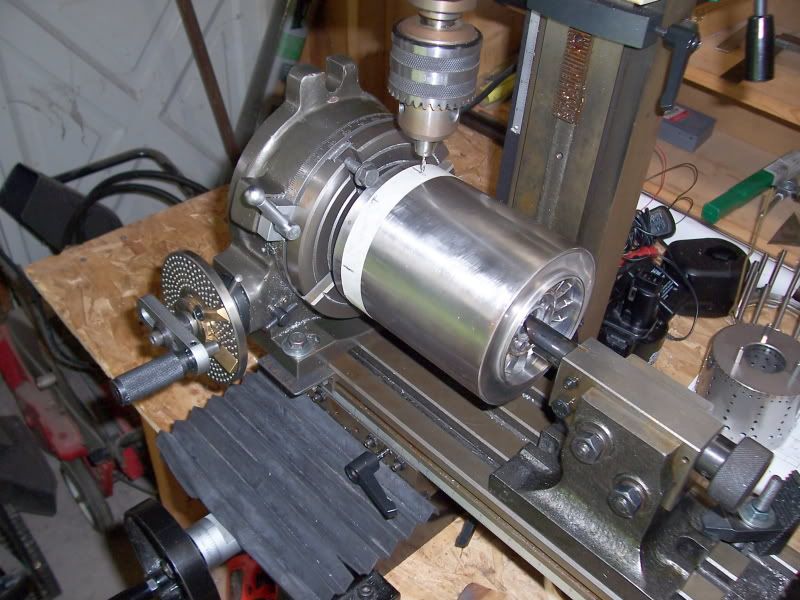
The diffuser has 13 wedges so a dividing head is needed to space the holes accurately, additionally only 6 of the wedges are used for the retaining bolts. The result is a fairly odd drill pattern. The masking tape was used to mark the wedges to be drilled, as drilling the wrong wedge would scrap parts that take many hours to make. So, after about 3 hours of fiddly setup the holes have been drilled ;D
Regards,
Steve.
rythmnbls
Well-Known Member
- Joined
- Jan 14, 2012
- Messages
- 115
- Reaction score
- 31
A minor update.
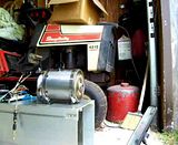
The glow plug mounting boss has been machined and welded to the combustion chamber. A start has been made on getting the test stand ready.
Photo of the test stand.
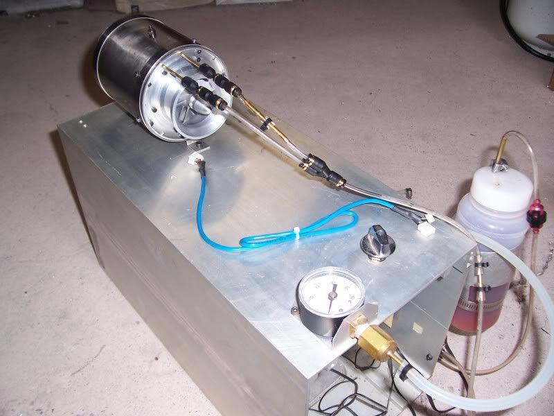
I still need to make the gas pre-heat supply line, the compressor spinner / nut needs to be replaced with a unit that has an embedded magnet and the rotor still needs to be balanced.
Thanks for reading
Steve.
The glow plug mounting boss has been machined and welded to the combustion chamber. A start has been made on getting the test stand ready.
Photo of the test stand.
I still need to make the gas pre-heat supply line, the compressor spinner / nut needs to be replaced with a unit that has an embedded magnet and the rotor still needs to be balanced.
Thanks for reading
Steve.
rythmnbls
Well-Known Member
- Joined
- Jan 14, 2012
- Messages
- 115
- Reaction score
- 31
Apart from balancing, the engine is finished.
Photo of the all the parts.
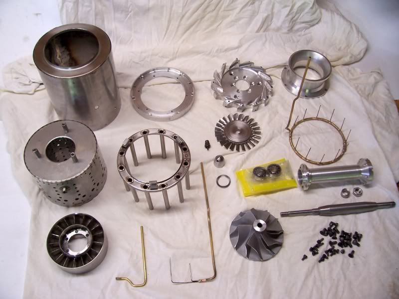
Photos of the assembled turbine.
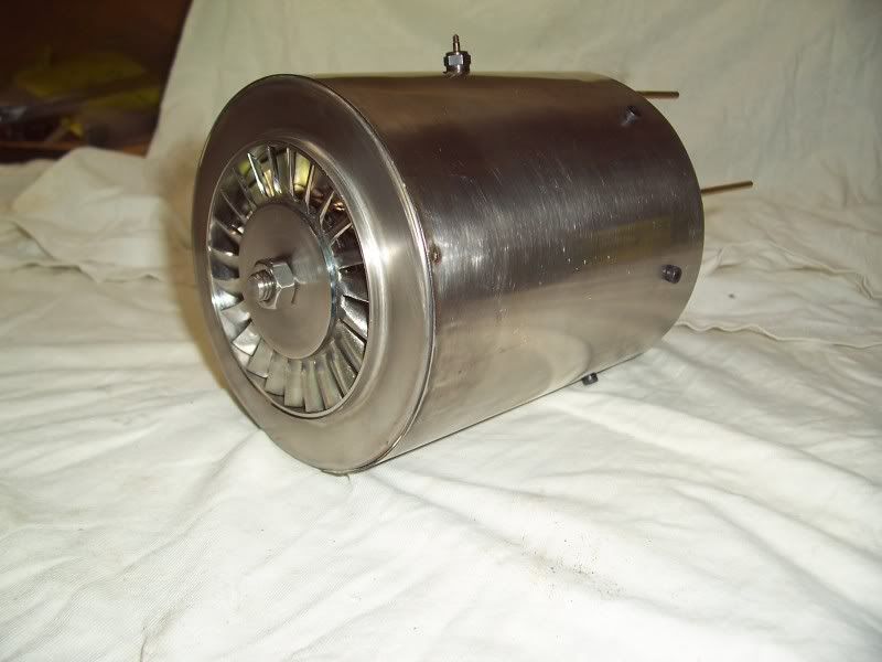
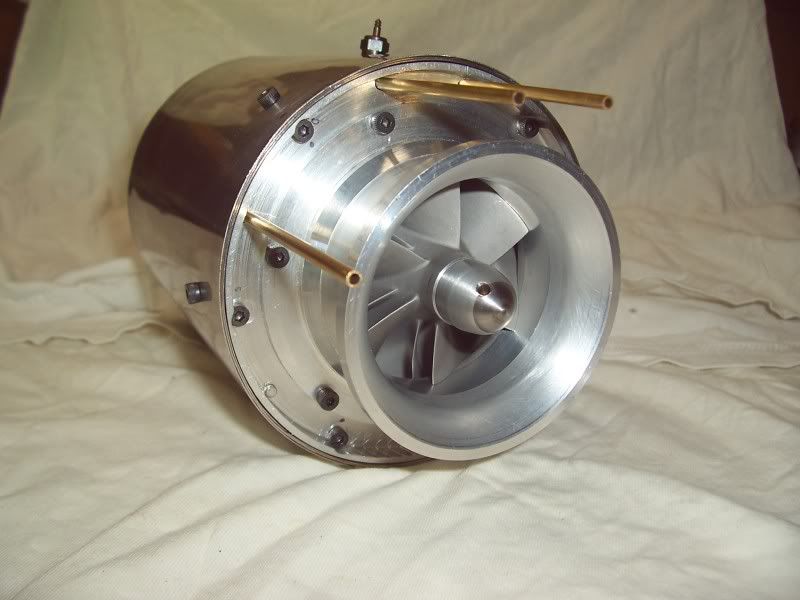
It looks like I will have to build a dynamic balancer next, until that is complete the engine will be statically balanced for initial ( low speed ) test runs. The plan is to run it next weekend, and take some video")
Steve.
Photo of the all the parts.
Photos of the assembled turbine.
It looks like I will have to build a dynamic balancer next, until that is complete the engine will be statically balanced for initial ( low speed ) test runs. The plan is to run it next weekend, and take some video
Steve.
J
JorgensenSteam
Guest
I think I would wrap it in about 6 layers of Kevlar.
If one blade lets go, or the bearings give out, then it will all go, and those blades will go through anything and everything.
Just a thought.
If one blade lets go, or the bearings give out, then it will all go, and those blades will go through anything and everything.
Just a thought.
rythmnbls
Well-Known Member
- Joined
- Jan 14, 2012
- Messages
- 115
- Reaction score
- 31
I ran the engine for the first time today, not a lot to report as this was just a propane run.
The engine self sustained at 10K rpm, which I'm happy with. Unfortunately my propane regulator wont allow higher speeds so faster runs will have to wait till I'm ready for a kerosene fueled run.
Here is a very brief clip of the run, you can hear the engine flame out when I accidentally cut off the propane. You can see the NGV is glowing a bit, I'm guessing at 10K rpm there's probably not enough airflow to cool it adequately. Normal idle speed is 33k.
There was some slight distortion of the NGV during cool-down which caused the turbine wheel to rub, a couple of minutes in the lathe took care of it.
Photo of the combustion chamber after the run.
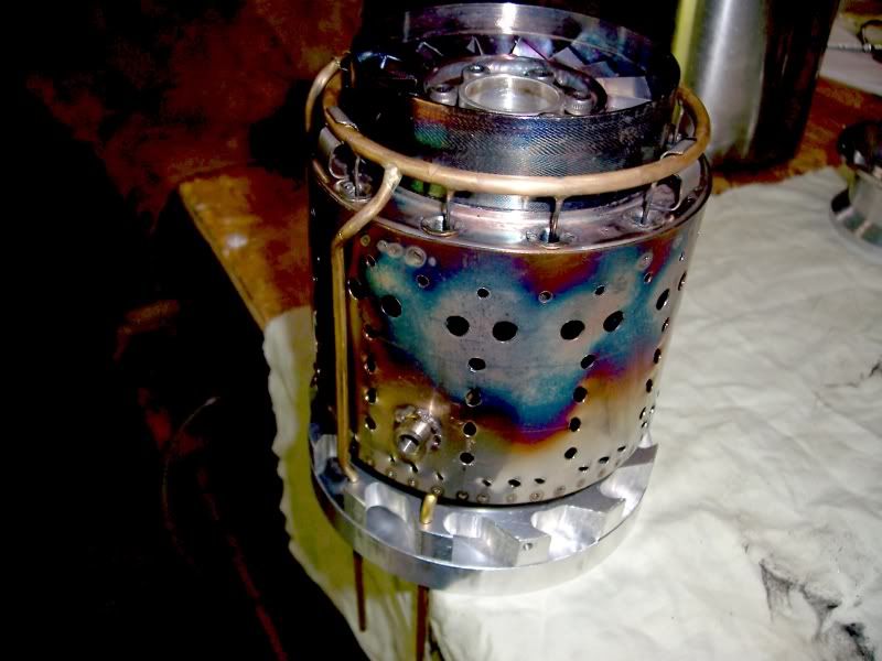
A photo of the rear end after reassembly
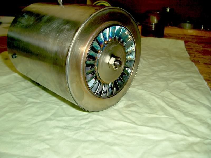
Mechanically it looks good so I hope to post a video of it running on kerosene soon.
Regards.
Steve.
The engine self sustained at 10K rpm, which I'm happy with. Unfortunately my propane regulator wont allow higher speeds so faster runs will have to wait till I'm ready for a kerosene fueled run.
Here is a very brief clip of the run, you can hear the engine flame out when I accidentally cut off the propane. You can see the NGV is glowing a bit, I'm guessing at 10K rpm there's probably not enough airflow to cool it adequately. Normal idle speed is 33k.
There was some slight distortion of the NGV during cool-down which caused the turbine wheel to rub, a couple of minutes in the lathe took care of it.
Photo of the combustion chamber after the run.
A photo of the rear end after reassembly
Mechanically it looks good so I hope to post a video of it running on kerosene soon.
Regards.
Steve.
doubleboost
Well-Known Member
- Joined
- Feb 23, 2008
- Messages
- 122
- Reaction score
- 6
Hi
Steve
Looking good
The burn pattern is in the correct place on the flame tube
More gas and it would have been away
John
Steve
Looking good
The burn pattern is in the correct place on the flame tube
More gas and it would have been away
John
- Joined
- May 3, 2011
- Messages
- 410
- Reaction score
- 67
she's alive ;D ;D
Boxfordian
Active Member
- Joined
- Jun 8, 2011
- Messages
- 39
- Reaction score
- 0
Hi Steve
Good work ! Am following on the GTBA site anyway, but thought I'd say 'Hi' here too, small world aye !
Ray ;-)
Good work ! Am following on the GTBA site anyway, but thought I'd say 'Hi' here too, small world aye !
Ray ;-)
rythmnbls
Well-Known Member
- Joined
- Jan 14, 2012
- Messages
- 115
- Reaction score
- 31
Thank you all for the kind words.
Hi Ray !, small world indeed
The first run on kerosene was attempted today, the result of which I would call a partial success. The attempt was aborted just as the turbine was coming up to speed due to a tachometer failure, it seems to be getting interference and giving lower than normal readings. I need an accurate tach for testing, so for safety's sake I shutdown when I realized the readings weren't accurate.
On the plus side the turbine itself seems good.
Here's a video of the run, at 1:15 was when it was decided to shutdown, I'm estimating RPM at this point is about 15-20k (the tacho is reading 7k), the flames are normal and usually disappear as rpm increase and approach idle speed.
Thanks for reading.
Steve.
rythmnbls
Well-Known Member
- Joined
- Jan 14, 2012
- Messages
- 115
- Reaction score
- 31
There were some discussions earlier in this thread regarding balancing and balancers, I ended up building the balancer published by the GTBA. If you have access to the site and the GTBA CD, you can find the schematics in newsletter 34 published in 2001. This is a standalone device, no computer or software needed.
Photo of the balancer electrics.
Photo of one of the sensor arms. The red material is 1.6 mm fiberglass. The piezo sensor is 20mm in dia.
Photo of the setup, visible on one of the blades is a small piece of rubber hose used to create an imbalance point for calibration.
Rather than build a dedicated frame for balancing, I used the lathe. The thinking is the balancer hardware needs to be rigid, be able to absorb vibrations and be level. The lathe fits that bill better than anything I could build, so it got the job, plus I would only have to make the sensor arms.
Hopefully this answers some of the questions raised earlier.
Regards.
Steve.
Last edited:
rythmnbls
Well-Known Member
- Joined
- Jan 14, 2012
- Messages
- 115
- Reaction score
- 31
Been a while since I've updated this due to an unexpected health problem that laid me up for a month.
Engine testing is progressing, initially I've been concentrating on getting exhaust gas temps (EGT) down to reasonable levels. The first couple of runs EGTs were around 720 degrees C which is at least 100 degrees too high. The cause was traced to case leaks and a rubbing compressor wheel both of which have been addressed.
Testing methodology has been to run the engine at a set speed starting at 35k rpm, burn a full tank of fuel ( 500ml ), shutdown and inspect critical parts, increase speed by 5K rpm and repeat the entire test. Maximum speed attained so far is 50K rpm.
Here's a video clip of the test at 45K rpm.
[ame]http://youtu.be/fUZqlS1nt_w[/ame]
The start was a bit hot as the starter, a dremel, was removed too early forcing the turbine to work harder than necessary to get up to speed, plus I was a bit heavy handed on the fuel control.
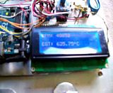
Another ( very blurry ) clip showing the arduino displaying RPM and EGT for the 50K run. The temps displayed here are about where they should be, so I'm pleased with progress so far.
Thanks for reading.
Steve.
Engine testing is progressing, initially I've been concentrating on getting exhaust gas temps (EGT) down to reasonable levels. The first couple of runs EGTs were around 720 degrees C which is at least 100 degrees too high. The cause was traced to case leaks and a rubbing compressor wheel both of which have been addressed.
Testing methodology has been to run the engine at a set speed starting at 35k rpm, burn a full tank of fuel ( 500ml ), shutdown and inspect critical parts, increase speed by 5K rpm and repeat the entire test. Maximum speed attained so far is 50K rpm.
Here's a video clip of the test at 45K rpm.
[ame]http://youtu.be/fUZqlS1nt_w[/ame]
The start was a bit hot as the starter, a dremel, was removed too early forcing the turbine to work harder than necessary to get up to speed, plus I was a bit heavy handed on the fuel control.
Another ( very blurry ) clip showing the arduino displaying RPM and EGT for the 50K run. The temps displayed here are about where they should be, so I'm pleased with progress so far.
Thanks for reading.
Steve.
rythmnbls
Well-Known Member
- Joined
- Jan 14, 2012
- Messages
- 115
- Reaction score
- 31
Here's a clip of another test run, top speed was 55K RPM, this clip will give interested viewers an idea of fuel consumption of these engines. They are very thirsty.
[ame]http://youtu.be/C6BHWNTmCd0[/ame]
Regards,
Steve.
[ame]http://youtu.be/C6BHWNTmCd0[/ame]
Regards,
Steve.
rythmnbls
Well-Known Member
- Joined
- Jan 14, 2012
- Messages
- 115
- Reaction score
- 31
Thanks for the comment.
Top speed with the existing turbine wheel is about 60K, this wheel is made of inconel 625 and isn't strong enough for a full speed run which is about 115K, I have a slug of inconel 718 and plan to use that for a replacement wheel, but I don't have the tooling to slice it up yet, plus I need a temp controlled oven to heat treat it. The tooling and the oven are side projects that are in the works, but finding the time is always the challenge
Regards,
Steve.