Gas Turbine build, pictorial build log.

Home Model Engine Machinist Forum

Help Support Home Model Engine Machinist Forum:

This site may earn a commission from merchant affiliate links, including eBay, Amazon, and others.
Very nice
Steve
A bit of a black art hole patterns on flame tubes :bow: :bow: :bow:
Watching this thread with great interest
John
 
Very nice progress, I'll be watching this post with interest. I wanted to build one but haven't got to it yet. Seeing your progress has renewed my interest.

James
 
Update.

The combustion chamber welding is done. The vaporiser tubes are done and installed.

Photo here.
100_0978.jpg


A start has been made on the plumbing, the lube line is done.

Photo here.
100_0983.jpg


Photo of the major parts so far ..
100_0980-gamma.jpg


Next up are the fuel supplies and the outer case. Then it will be time to start thinking about a test stand. ;D

As always, there are a many more photos at the photobucket site.
http://s87.photobucket.com/albums/k142/madluther/Turbine 2/


Steve.
 
Great build log Steve. Lots of pictures. Definately worth a karma point
 
Thanks for the karma point Herbie, I'll put a Coopers in the fridge for you ;)

Today saw the fuel ring completed, not my favorite part to make, very fiddly plus the engines performance can be greatly affected by a bad ring.

Photo of punching holes for the injector needles, the holes are punched rather than drilled to avoid filling the ring with swarf. The ring is supported by the grooved tool to stop it flattening out during the punching.

100_0988.jpg


Testing the fuel ring after brazing the needles.

100_0993.jpg


Photo of the fuel ring installed on the combustion chamber showing the routing of the feed pipe. It is important that the feed pipe avoid covering any air holes. I still have to make the clips that secure the fuel ring to the combustion chamber, the ring also needs to be cleaned of brazing residues.

t2_fuelring1.jpg


Thanks for reading.

Steve.
 
Hi Steve. I do love a cold Coopers. Will save it for the christening of the engine which doesn't seem too far off now.
 
The outer case is done, it is made from 316 stainless sheet 0.5mm / 0.020" thick. Its basically a flange and an outer wrapper spot welded together.

Here's a photo of the parts.
case_parts.jpg


Photo of the setup used to hold it together for welding.
100_1017.jpg


The case after welding
100_1020.jpg


Photos of the case fitted to the engine.
100_1026.jpg


100_1028.jpg


I still have to make the pre-heat gas line, the front compressor spinner with an embedded magnet and drill and tap the case securing holes. After that I need to think about balancing in preparation for some test runs.

Thanks for reading.

Steve.

 
Steve. Superb bit of workmanship there. Can you tell us a bit about your spotwelder please. :bow:
 
Nice build!

I don't mind saying I love the sound of a turbine, but frankly scared of the top speed....Lots of forces in a very small package!

Thanks for taking us along!

Dave
 
Herbie,
The spot welder is a commercially made unit from Hobart model # HSW-15.

Blighty,

Up until now I have only statically balanced my turbines, but this one will need something better, I'm looking at a few designs published by the GTBA at the moment, no firm plans yet.

Regards.

Steve
 
statically balanced... as in "the wren way"?

i to was looking for balancing stuff on the GBTA, that's why i joined. the only thing i could really find was plans for the frame/mechanics, but not much on the electronic side of thing. plus there was nothing about the software needed to run the thing. i was a bit miffed at this as the GBTA have a nice balancing machine on there bench at all the engineering shows they go to, with a sign that says "you can make this, details on the GBTA web site" don't know if its me or not, but i cant find a single all in one build thread.... i.e build the frame with these drawings, make the electronics here's the schematics and download the software to run it here.

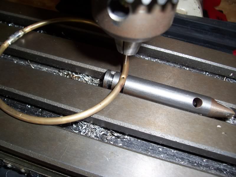
when i balanced my turbine i went the wren way. tried and tested method i'm sure, but i'm not 100% convinced in it. not so much the idea, but me doing it..... yes, it now stays put when you rock it, but is it REALLY balanced?
 
There should be some mention of the Dynams balancing software on GTBA. I used it when building my spindle and can say that it's worth buying. It's not exactly cheap, but if you intend to use it more than once, it's doesn't really cost much.
 
Dynams doesn't need a frame, but can be used with one. You just mount accelerometer sensors to your engine or whatever. That's why I decided on the software. By the time I made the balancing rig, the circuitry, with a motor to drive it, it would have cost much the same. I've had Thomas's design saved on my computer for a decade and never built it. I probably would have if I was more involved in electronics. Thomas's pages on the little KP-31 turbine got my gears turning and I bought the compressor wheels long before I had any machining tools. now I just have to get around to building it. He was involved in the Lambert Kolibri design using this compressor.

Just send. Mr. Koncz an email for Dynams pricing. There are two options.

Greg
 
What are you doing for bearings, lube, and cooling? I see three notches at the front of the shaft tunnel and you've got one lube line coming in. Are the others for bleed air cooling? Where does the oil return?
 
I see three notches at the front of the shaft tunnel and you've got one lube line coming in. Are the others for bleed air cooling?

Yes, this is standard practice these days.

Where does the oil return?

The lube system is like a 2 stroke engine, the fuel consists of a mixture of kerosene and 3-5% of a synthetic two stroke oil. The bleed air and fuel mix create a lube mist which cools and lubricates both bearings, the mist exits the rear bearing and is lost. There is no return. Lube rate is very low, one or two drops per second.

The bearings are preloaded full complement hybrid ceramic ball bearings.

Regards.

Steve.
 
Back
Top