G-Code error HELP!

Home Model Engine Machinist Forum

Help Support Home Model Engine Machinist Forum:

This site may earn a commission from merchant affiliate links, including eBay, Amazon, and others.

Mike Ginn

Well-Known Member
HMEM Supporting Member
Joined
Mar 5, 2020
Messages
322
Reaction score
134
Location
UK
Guys
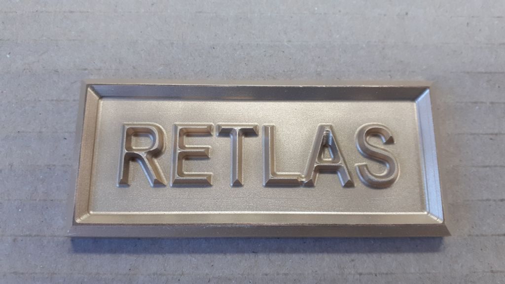
I have coded a name plate for my Wyvern using DXF (for outline) to CAMBAM (for text) and G-Code from CamBam with 99,000 lines into MACH3 and a KX1 mill. Machining with a 0.3 V cutter. Dedicated computer running XP with no AV or any attachments (as per MACH3 instructions), 2Gb of ram.

I have machined 2 small plates having about 50,000 lines and they were OK.

Each time I machine the larger plate I get a cut though the Wyvern and also through Westbury. Initially the cutter path on MACH3 does not show these unwanted cuts. I have made these plates twice and the unwanted cuts occurs on the 3rd pass and in the same position on each plate.

Possible explanation could be memory/disc data transport issue. I could try another computer but it needs a parallel port and a lot of hassle setting up.

Have any of you experience this type of error - do you have any suggestions? I would like to keep with MACH3 and Linux is a no-no!

Many thanks

Mike

1646914317131.png
 
Could try splitting the code up into smaller sections, maybe run CAMBAM for each pass by altering the start and finish heights. That would eliminate the file size problem and could be run on the damaged part as a test.
 
Hi Jason
The mystery deepens! I looked at the tool path on a large screen and found that there was a single 0.3mm cut line through the text. If I split the text and coded each line separately it was fine. I tried many variants but cannot pin down the cause of the problem and I don't have the skill to edit the G Code. My solution is to cut to full depth the top half of the name plate and then load up and cut the bottom half. I have modified the design to provide cutter overlap.

I guess I can conclude that the XP computer is OK. Maybe there are some entities left in the dxf drawing which I cannot see. I note that the unwanted cuts are parallel to the plate edge and equally spaced. Also the cut between the unwanted cuts is a curve so I conclude that I don't have a random problem but one which is driven by some unknown entity.

At least being almost bald I can't pull my hair out!!

Thanks for your suggestion

Mike
 
Suggestion: load the G-code file into a text editor like Notepad++ (with line numbers turned on) and search for lines containing Z -0.3 to identify the offending motion commands. Focus on 3rd pass and expect a large X axis move (several cm) in the same line or just after. If you can find the lines with the unwanted cuts, changing the Z -.03 to Z+1.0 could resolve the problem. There may also be some issues with the left side of the Wyvern W. You could verify G-code fixes by using the single step feature in the Mach3 tool path window.
 
I would post the CB and nc files on the CamBam forum where there is a lot of expertise. Looks to me like a clearance plane issue/stock surface issue.
 
It seems to me that there is a rectangle hidden in the original DXF file. Would you have a deactivated layer there?
Have you started with a rectangle and then did and offset and forgot to delete the original shape?
I would look for something like that in the CAD file.

Plate_error.jpg
 
Another possibility is that the mystery object, if it's there, is set to the same color as your CAD background color. I've run into that with other software packages, CAD wouldn't be that much different.
 
Could it be the machine skipping the end point of an arch?
I had kind of the same problem on a CNC mill when we started using CAM with dynamic milling, crushed a 40mm cutter in the side of a 200mm steel cube it was contouring (could not air run as it was over 1 hour even whit max feedrate. It turned out the machine missed the end point of an 0.001mm arch and proceeded to close the circle digging into the piece (no error in the Gcode), solved by searching for the last coordinate after the crash and deleting a few lines altogether. It didn't mattered at all as it was less than 1mm in total movement.
 
Guys
Many many thanks for the suggestions and ideas to solve/understand my toolpath problem. Special thanks to Rich who kindly corrected the G-Code.
However I really wanted to understand why it was happening. I started by suspecting my very old XP machine (requirement for Mach3 when I installed). I then suspected that there could be an issue importing the dxf file into CamBam but since it was only the outline and the text was inserted in CamBam it seemed unlikely. I then looked very closely at the tool path at high magnification and since I knew where the cut was I was able to see the single path which I show in the images below. I then split the name plate into the upper and lower text and arranged for a suitable area overlap and, interestingly, the Wyvern cut correctly but the lower text did not. I then experimented with the lower text by exploding the text - same problem - and then splitting the text. I found that splitting between the t and b in Westbury altered the tool path and I did not get the unwanted cut. As you can imagine I looked very carefully at the tool paths at high magnification. For the forth time I started the cut which took 9 hours - 0.1mm depth to 0.6mm and feed rate 125 at 7000 rpm with a 0.3mm 10 deg cutter. It worked as shown below. However using a lope shows small bridges on the e and g. this was caused by the spacing at those points being less then the cutter width of 0.3. The solution would be to enlarge the text/name plate, use a smaller cutter (!) or live with it. I'll live with it since I only observed the bridge when I posted this image.

The pocket feature of CamBam clearly has a bug. I'm sure that many of you will say to use a more efficient program but I fine CamBam dose what I want although I am open to suggestions. I need to be able to import dxf files and insert text then generate toolpaths and G-Code for my Mach3/KX1 mill.

All this took about 50 hours including baby sitting the mill every 30 minutes to brush oil onto the cutting surface. I don't have misting as has been quite rightly suggested.

Full disclosure:- the hours of cutting did include several glasses of wine as my lubrication!

Again - thanks for your support.
Mike

1647254088873.png


1647254442641.png


1647254501135.png
 
Guys
Many many thanks for the suggestions and ideas to solve/understand my toolpath problem. Special thanks to Rich who kindly corrected the G-Code.
However I really wanted to understand why it was happening. I started by suspecting my very old XP machine (requirement for Mach3 when I installed). I then suspected that there could be an issue importing the dxf file into CamBam but since it was only the outline and the text was inserted in CamBam it seemed unlikely. I then looked very closely at the tool path at high magnification and since I knew where the cut was I was able to see the single path which I show in the images below. I then split the name plate into the upper and lower text and arranged for a suitable area overlap and, interestingly, the Wyvern cut correctly but the lower text did not. I then experimented with the lower text by exploding the text - same problem - and then splitting the text. I found that splitting between the t and b in Westbury altered the tool path and I did not get the unwanted cut. As you can imagine I looked very carefully at the tool paths at high magnification. For the forth time I started the cut which took 9 hours - 0.1mm depth to 0.6mm and feed rate 125 at 7000 rpm with a 0.3mm 10 deg cutter. It worked as shown below. However using a lope shows small bridges on the e and g. this was caused by the spacing at those points being less then the cutter width of 0.3. The solution would be to enlarge the text/name plate, use a smaller cutter (!) or live with it. I'll live with it since I only observed the bridge when I posted this image.

The pocket feature of CamBam clearly has a bug. I'm sure that many of you will say to use a more efficient program but I fine CamBam dose what I want although I am open to suggestions. I need to be able to import dxf files and insert text then generate toolpaths and G-Code for my Mach3/KX1 mill.

All this took about 50 hours including baby sitting the mill every 30 minutes to brush oil onto the cutting surface. I don't have misting as has been quite rightly suggested.

Full disclosure:- the hours of cutting did include several glasses of wine as my lubrication!

Again - thanks for your support.
Mike


Thank you for your careful work and notes.
Helping those who haven't done the stuff in learning better and faster when they will get there!

Just went a looking - - - - wonder if CamBam would work on WINE (linux)? Hmmmmmmmmm - - - -
 
The solution would be to enlarge the text/name plate, use a smaller cutter (!) or live with it.

You could also manually trim the end of the text e/g enough to allow the cutter to get through.
 
Whenever I see the word Linux the hairs on the back of my neck stand up and I am sure swirl around. I have had far too many bad experiences with Linux and vowed never to go down that route again. I Googled WINE and found lots of interesting wines!

Regarding the text bridge I would simply increase the name plate size and use larger text. I am kicking myself that I didn't notice the bridging on the first 3 plates. The dimension in the gap is 0.23 and to increase that to say 0.35 and change all the text size only increases the plate size by a few mm which I could live with. BUT can I face another 9 hours of machining for something that is hardly noticeable? I think I will leave it in the knowledge that if I wanted to correct the plate then a larger one will fit and cover the original fixing holes - which uses nails with turned down heads!

Maybe I will look at it again after I have completed a very difficult machining process on the crankcase of the Kiwi!

Mike
 
Although I originally would have gone with the suggestion that it was an unseen artefact in the original CAD design, I have seen a similar effect in one of my own pieces of work. A few years ago I was asked to engrave a brass master for lost-wax casting some lapel badges for my local model engineering society. I designed them in Vectric Vcarve and used its CAM feature to generate the gcode to run under Mach3. The engraving was going very well, except for one random and very much unwanted cut across part of the text not dissimilar to what happened here. I ended up reporting this to Vectric who responded very quickly and diagnosed it as an arithmetic rounding error somewhere in the code. Shouldn't happen, but did. Their recommended workaround pending a proper fix was to very slightly change the depth of cut throughout - when you are talking about errors in the 7th decimal place or something, that was enough to change things - and I was able to continue very successfully. I'm sure that the real problem was eventually fixed (and in any case it was a couple of versions ago) but they were trying to help me move on quickly to get my job finished, hence the fudge.

If you have a way of checking the gcode without actually having to run it, that might be worth a try?
 
Hi Nealeb
Yes I can check the G-Code without running it. My problem was that I had no clue where to start and I couldn't see the unwanted cut line. My previous experience with CamBam was always in profile mode and I have never had a problem. Pocket was a totally new experience and I just didn't know to visually check the toolpaths. The G-Code had 99,000 lines so running it would be tricky. My process is now to closely examine the toolpath and, if necessary, to force toolpath changes as per my earlier posting. I did try different cut depths to no avail.
I will contact the CamBam user group to get their view.
Thanks for your interest.
Mike
 
Does CamBam not have a simulation that you can run? I use F360 and find that better than looking at toolpaths as you can see where it has cut and where it has not, things like those bridges between letters clearly show in a different colour. It will also show any areas where the part has been cut through in a different colour so easier to pick up anything that should not be there.

Here you can easily see that there is a bridge between the bottom of the L and the A, also fillets left in the internal corners by the cutter as the 3D model had tight 90deg internal corners. I've switched off the tool paths to make it easy to see the actual part.

retlas blue.JPG


Blow it up big enough and you can see the actual scallops left by the cutter (0.2mm stepover) 2.0mm ball nose
retlas scallop.JPG


Finished part

904933.jpg
 
Hi Jason
I had no idea you could visualize the toolpaths in Fusion 360. The power of "our" Forum!
I could easily have solved the issue by enlarging the text had I realised that there could be a problem.
I recently downloaded Fusion 360 but have only worked through half of the first tutorial - I am using Arnold Rountree's tutorials. They have the advantage of matching the latest version of Fusion360 and also make it easy to follow/find the commands.
I really like your plates and aspire to such designs.
Two questions:- What size ball cutter did you use? How did you finish the plate. I sand blast mine and spray acrylic onto the brass
Mike
 
This is what it actually does, I took that screen shot at the end. The progress bar along the bottom will also flash up any collisions eg if you go deeper than the tool projection and hit the holder. The adaptive removes most of the purple waste but leaves 0.5 stock which you can then see being removed to leave the green finished surfaces. Fillets left by cutter as I did not bother to model them and they are wanted as it's a pattern for casting.


When running the simulation select "comparison" and that gives the results I show eg finished surface, material left and hopefully not cuts where they should not be.
f360 comp.JPG


I use a 4-flute 2mm dia carbide ball nose cutter

Bead blast finish with a very basic spot blaster

Low air only just to keep the chips away from the cutter, no lubricant on the brass.

 
Jason
Thanks very much for that info - I have a lot to learn! Am I right in thinking that you use F360 for the design and then generate the tool paths and also the G-Code all within F360? If so I really need to get going with F360! I looked a video of the 11cc cylinder and noted that there was no lubrication - only air to remove chips. The finish was good and I guess the extra rigidity of the KX3 over the KX1 (which I have) makes a difference.
Re brass. I was using soft brass sheet and found that there was a build-up on the cutter (0.3mm 10deg) which broke after a short time. Oil lub allowed the cutter to run for 9 hours and remain in good condition.
Very impressive work.
Mike
 
Back
Top