Flathead hit and miss engine???

Home Model Engine Machinist Forum

Help Support Home Model Engine Machinist Forum:

This site may earn a commission from merchant affiliate links, including eBay, Amazon, and others.
Like this----
IX0ZKr.jpg
 
It's been a long day of machining, but the cylinder and cylinder head are finished. I almost made a mistake---Where the manifold attaches to the cylinder I got two center drill divots in, then thought "Jeez, that doesn't look right!!"--Took a closer look at the drawing and seen that I had used the wrong dimension. Put in new center drill divots in the right place and kept going. No harm--No foul. The manifold will cover it up. Thats a crappy picture--must be time to charge my camera batteries.
9Y1tBX.jpg
 
I spent the lions share of today detailing parts to be built and working on my flywheel/fan. I purposely made the fan blades a bit too long, because I want to hold the hub in my 3 jaw chuck and turn the outer diameter for a perfect fit into the outer ring. Nothing looks worse on an engine than a wobbly flywheel, and I am taking great pains to avoid that.
HTv0zV.jpg
 
The flywheel is finished except for keyway, set screws, and final clean up. I'm impressed. the welding is all done on the side that doesn't show. The outer rim runs very true to the inner hub and vanes. This is due to the majority of set up work being done in the lathe (I mounted the hub in my 3 jaw chuck and turned the outside diameter of the "vanes" to "on size" with the inside diameter of the outer ring.) Outer ring was carefully tapped into place, checked for runout, and then carried very carefully to my main garage and welded there.
pLBTB5.jpg
 
No machining today. Had to go out and do some other business, and spent the rest of the day finishing a workable design of the intake/exhaust manifold. It ends up being a rather complex part, but fairly straightforward machining involved. There is a lot going on with that manifold.
kTLu1m.jpg

7uDWMO.jpg
 
Can't see that working Brian, the vacuum created by the intake stroke will pull the atmospheric intake valve closed rather than open it.:oops:
 
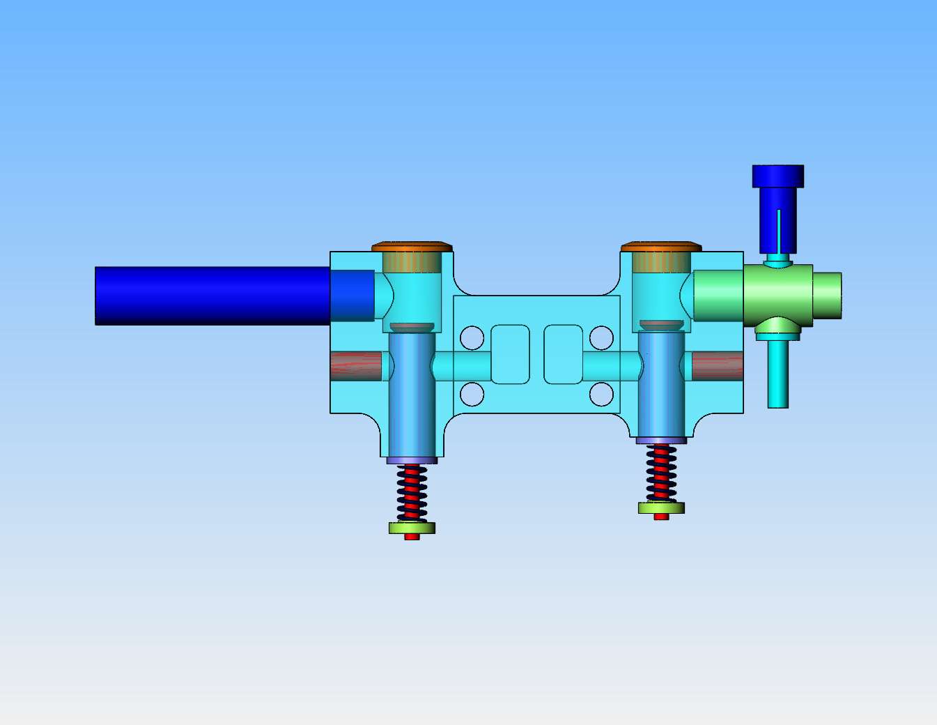
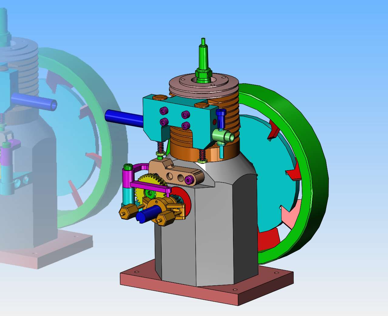
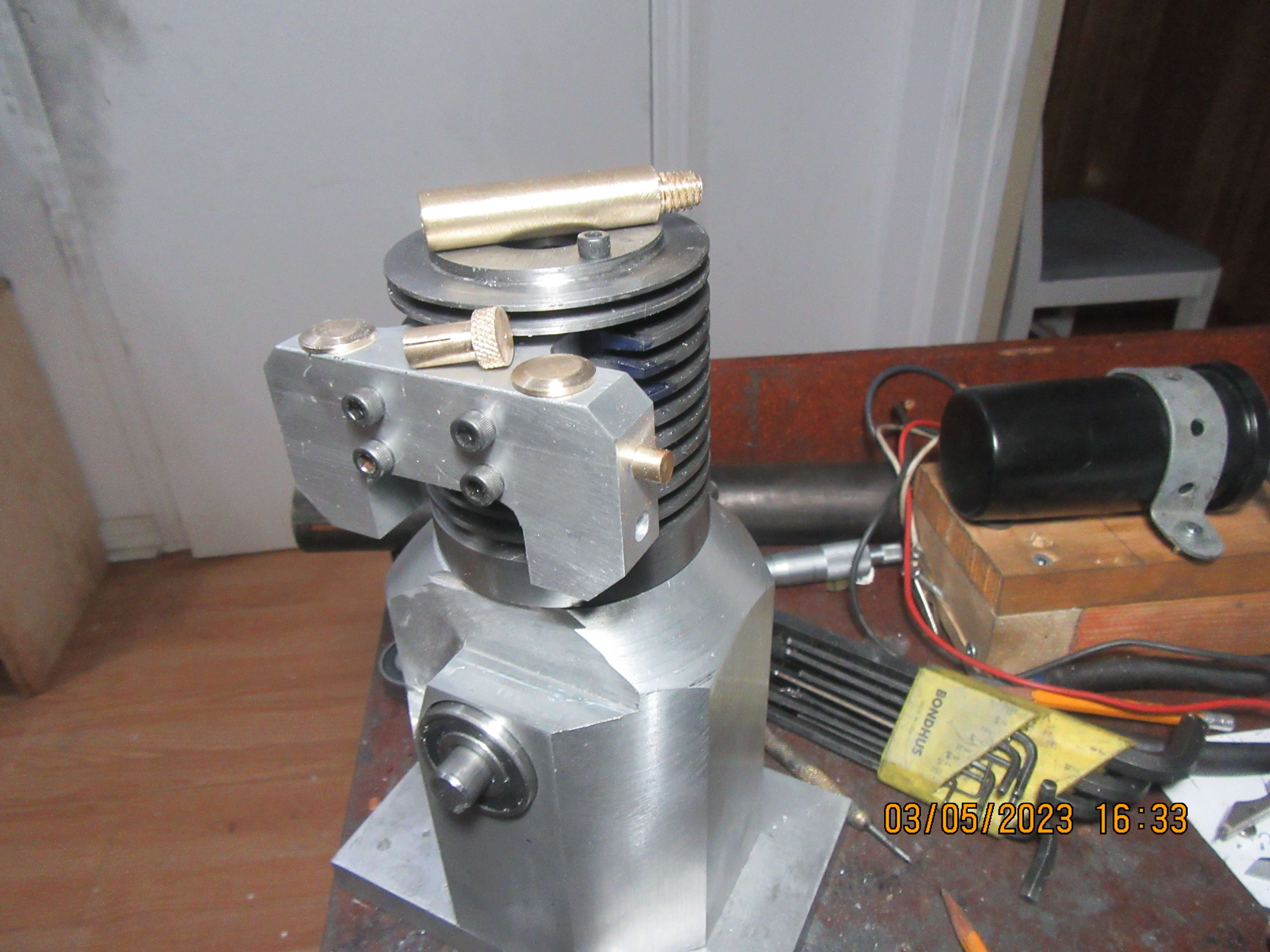
Yes exhaust is the wrong way round too

I did type more in my previous reply but seem to have cut it to post elsewhere rather than copy, here it is again

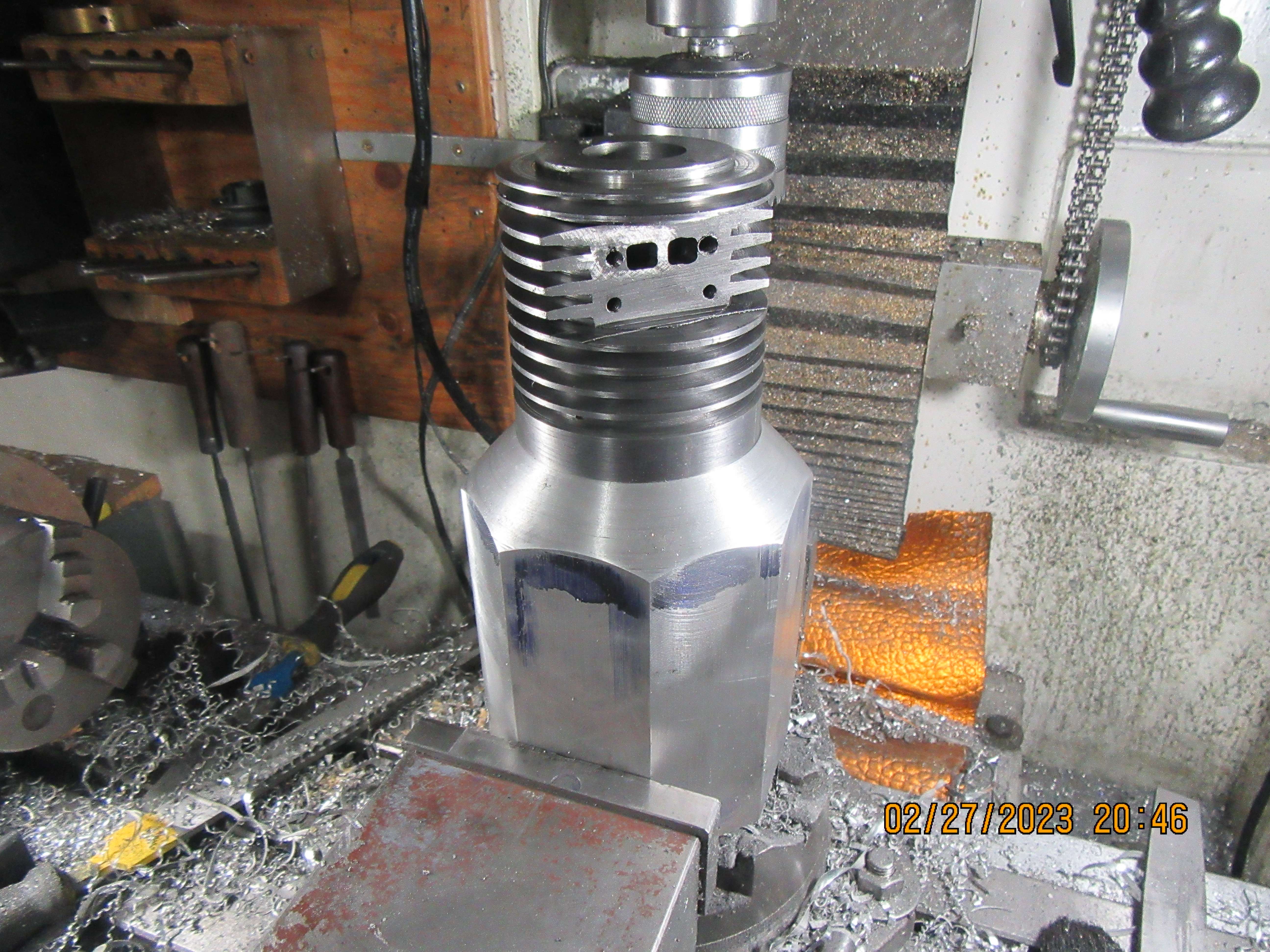
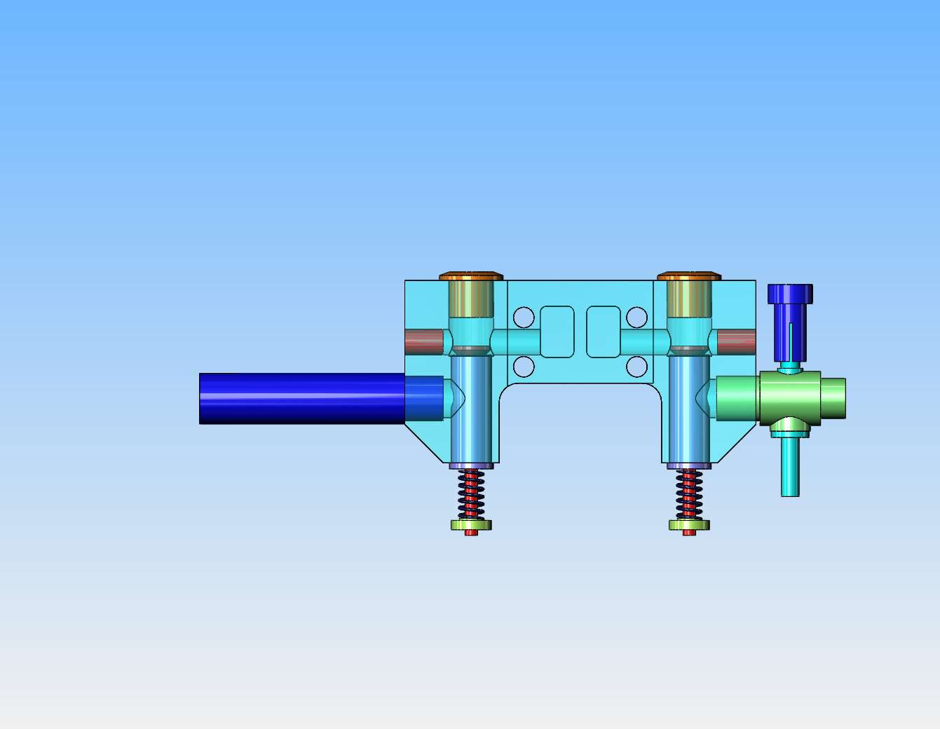
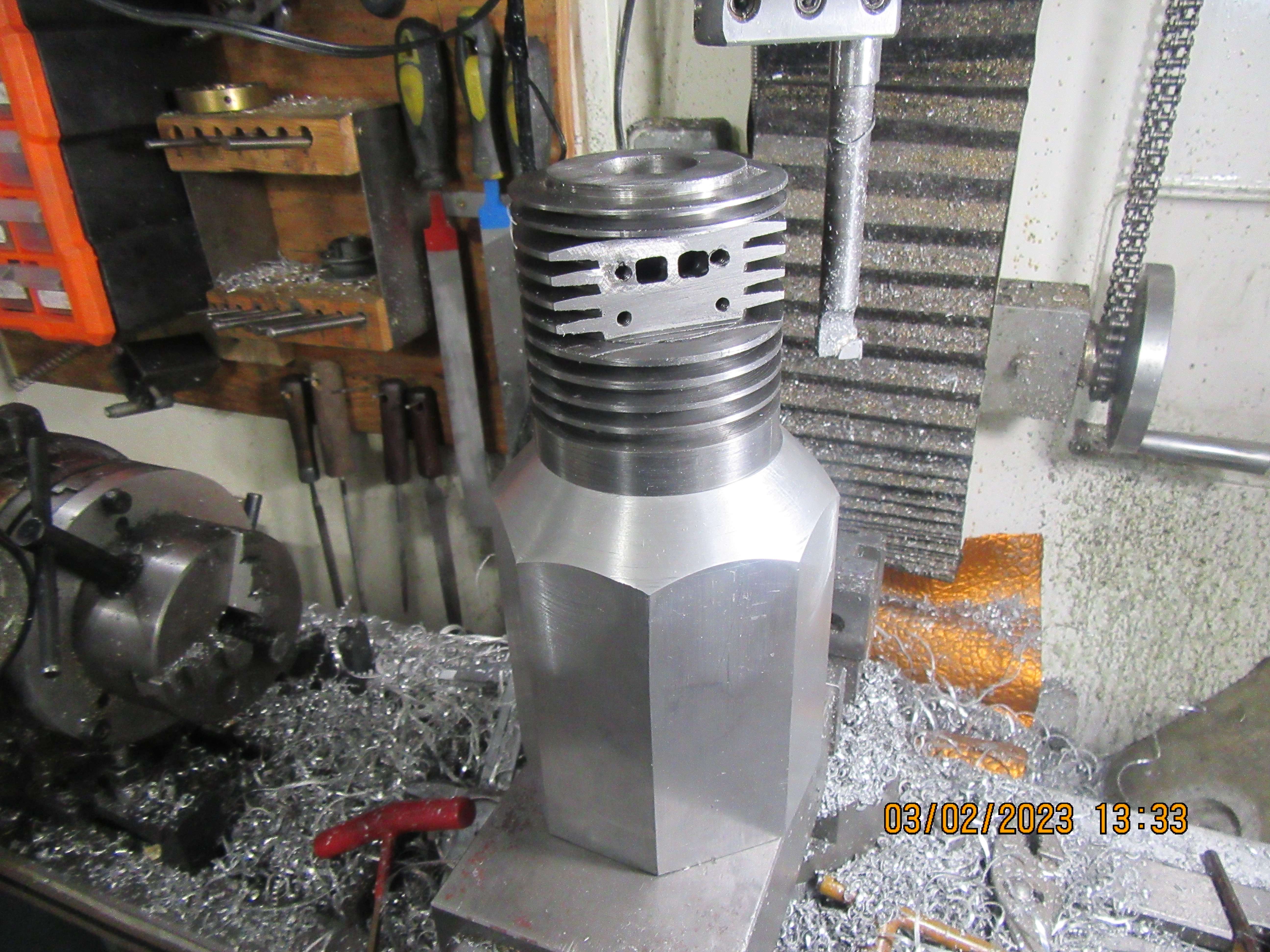
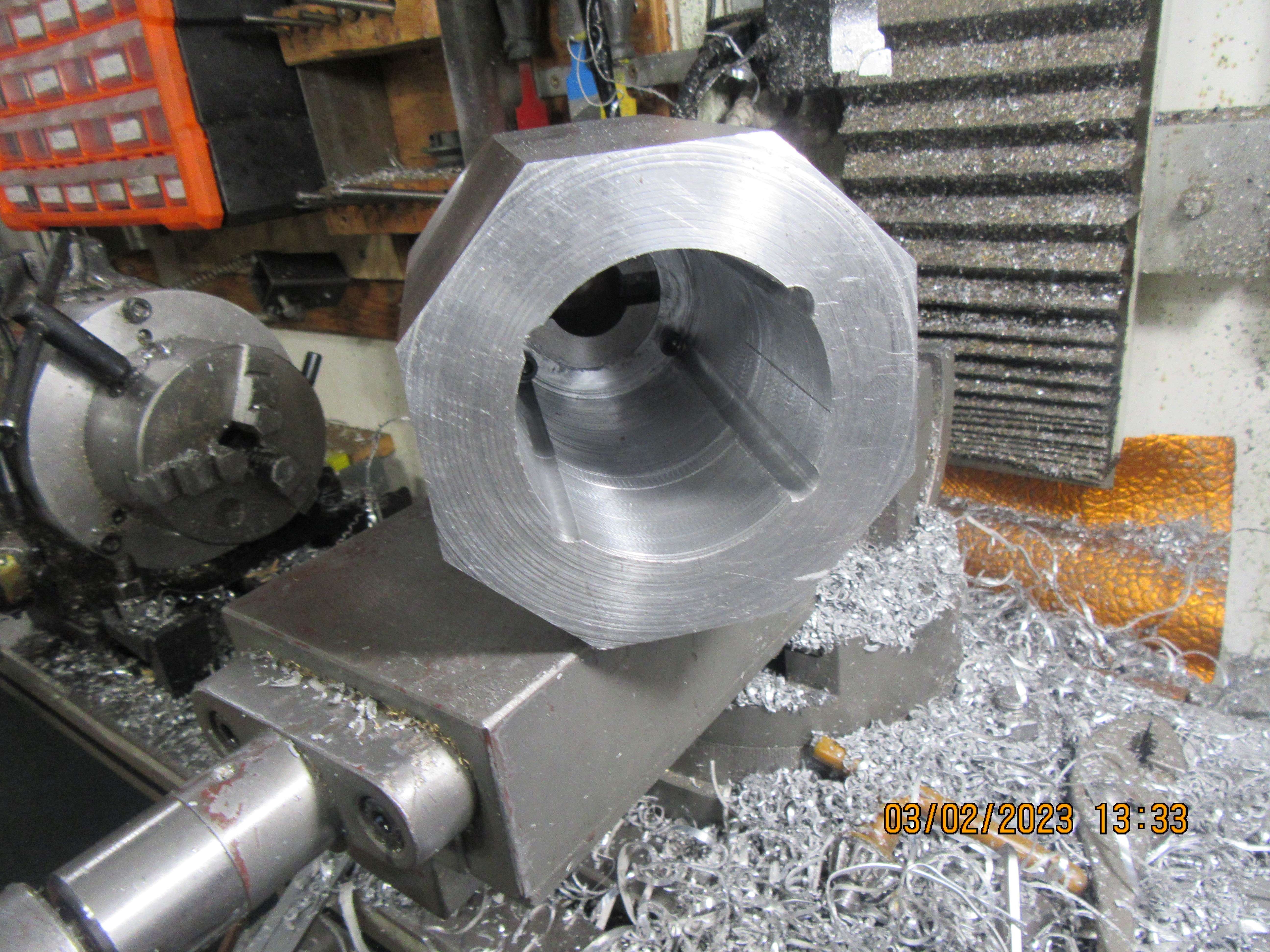
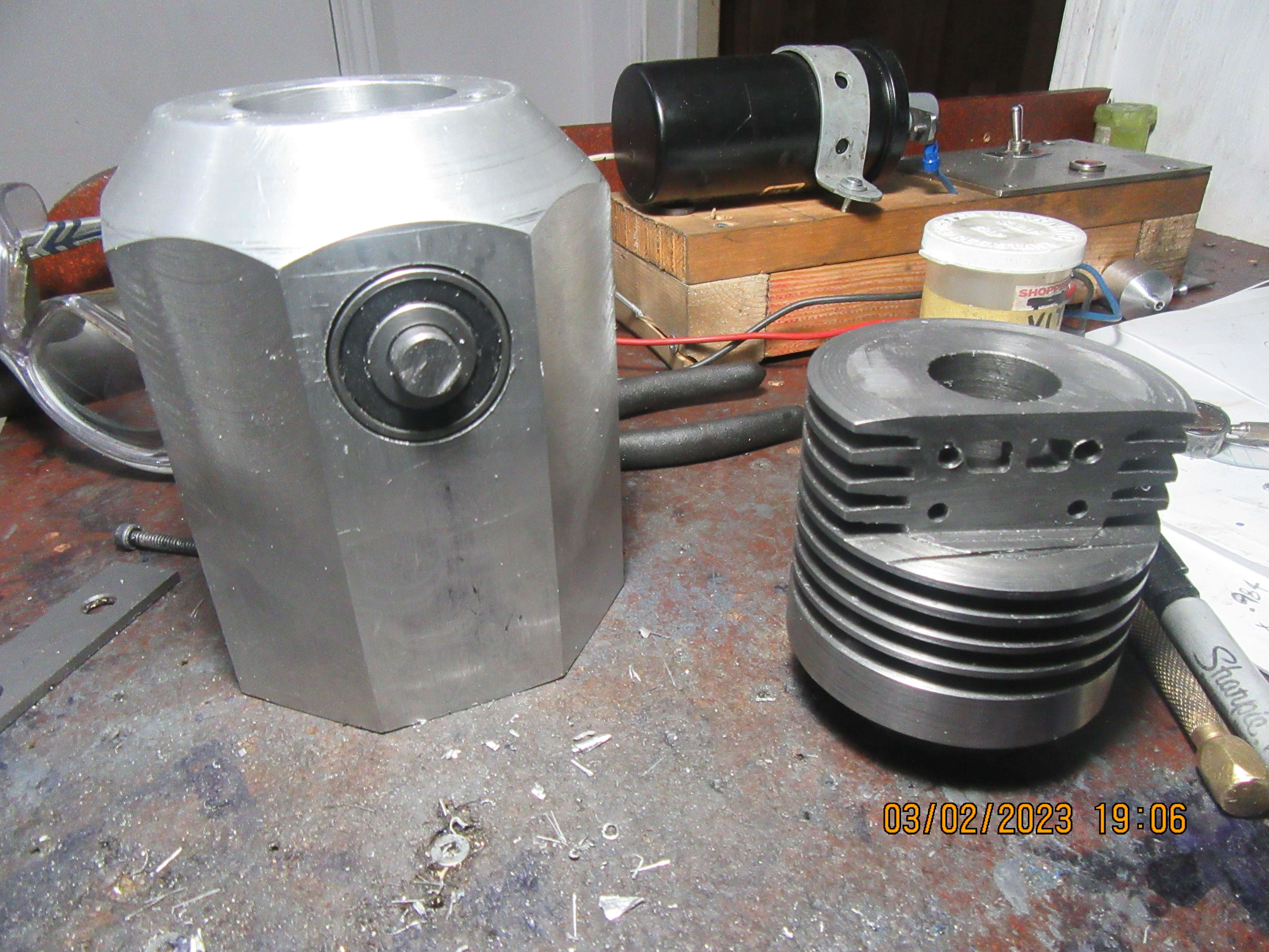
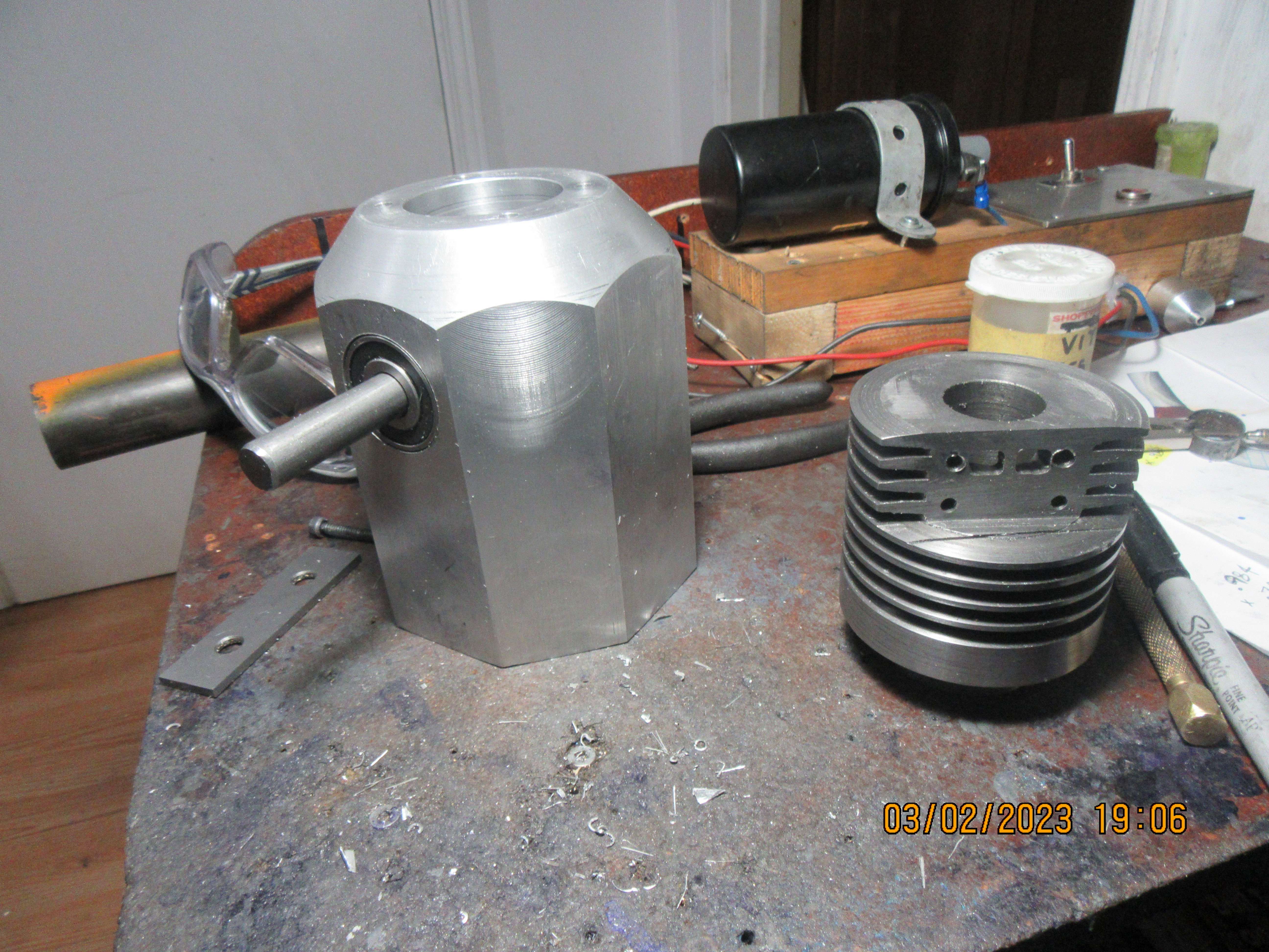
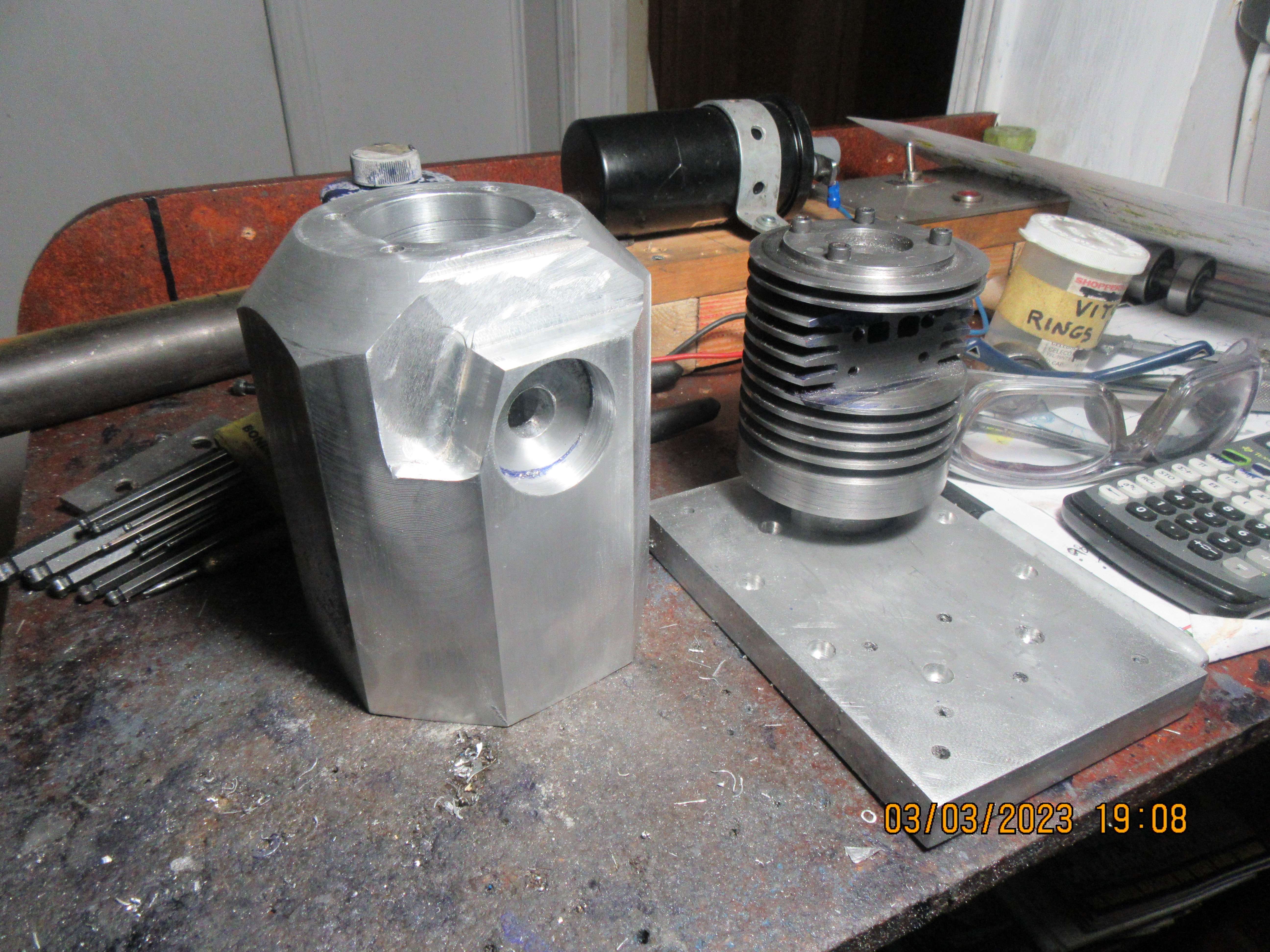
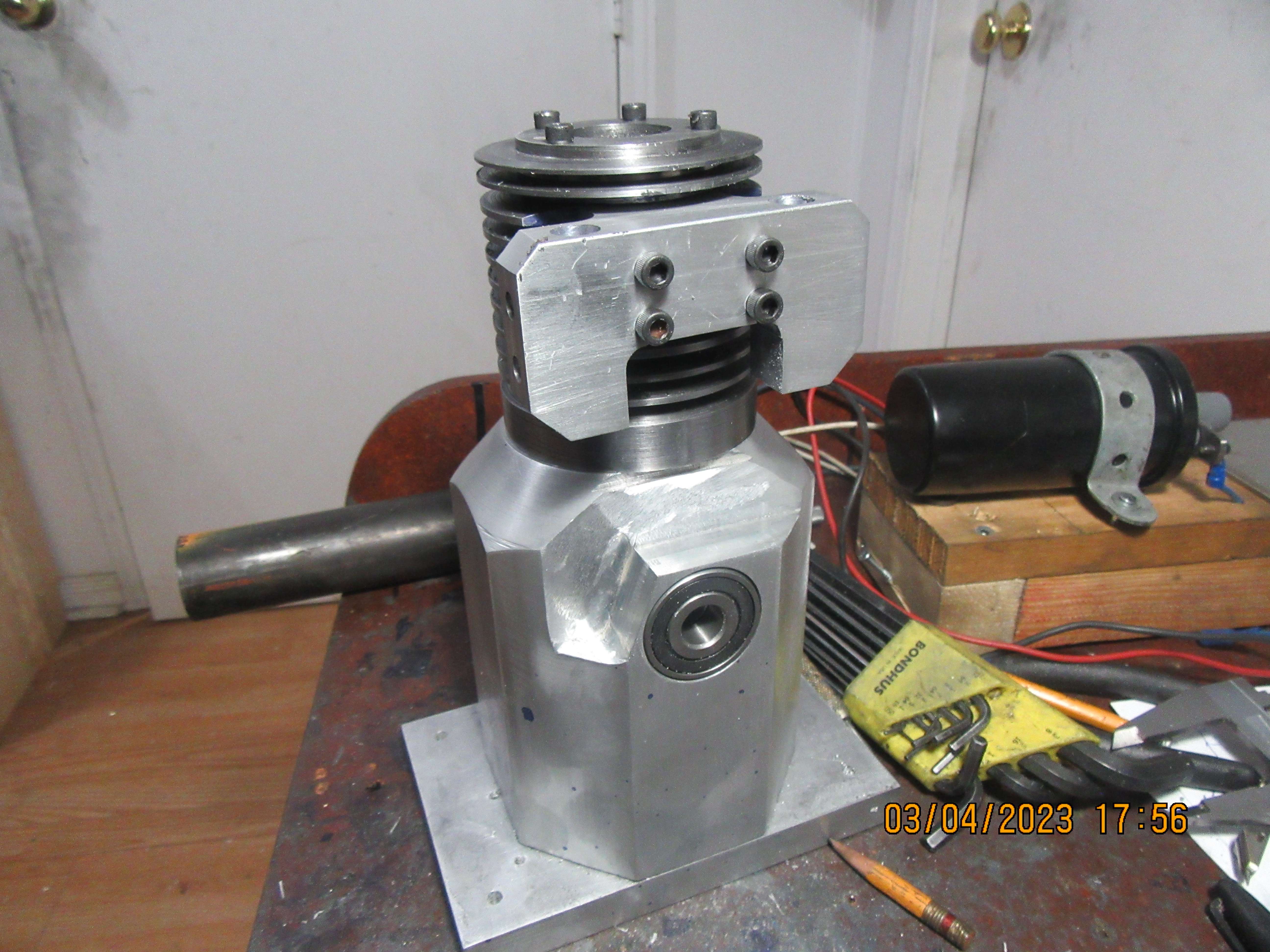
As you already have the passages and fixing holes in the cylinder you ar a bit limited to what you can now fit.

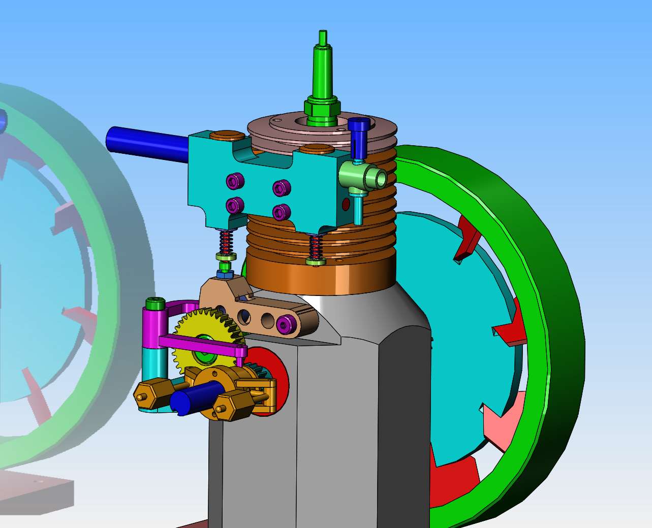
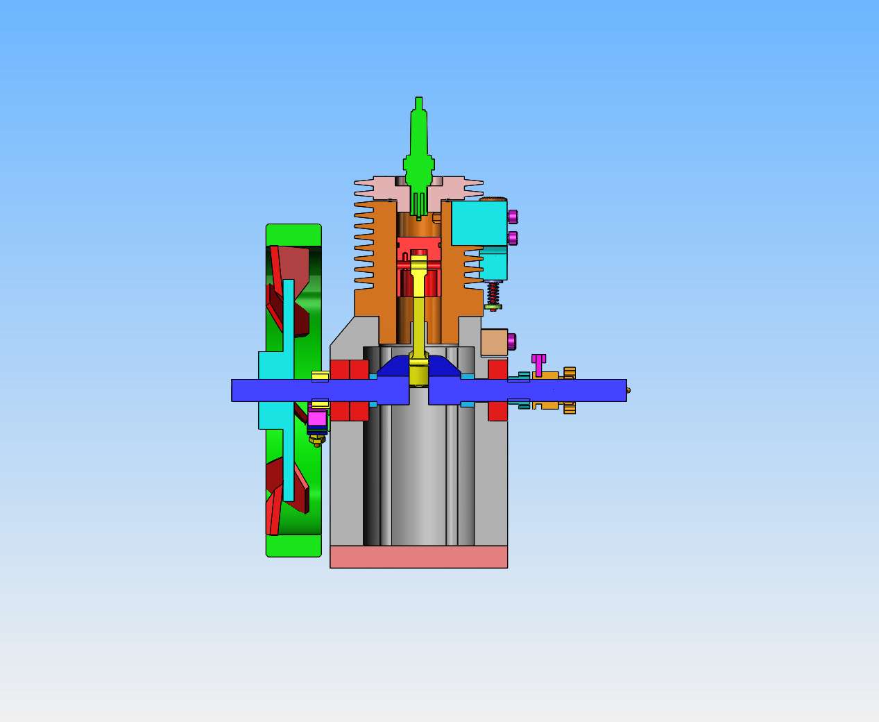
Option 1 would be to have th eintake valve stem point upwards with the valve head above the drilling to the cylinder and carb going into the side of the valve cage.

Option 2 if you want to keep it like a "flat head" with both valve stems pointing down would be to extend the bottom right corner of the block downwards so that the valve cage can be lowered and the carb inlet enter into the cage below the valve head
 
See--It's just like my mama told me--"Son, you should never be smoking rope when you're designing something!!!" Mama was always right!! I got up this morning ready to start detailing all these lovely manifold and valve parts and had notifications on all three of my forums that every thing I done yesterday was wrong. And dammit--it was all wrong.--So--start over again. Make the manifold and valve and things right, then reposition all the stuff bolted to the front of the engine that lifts the exhaust valve. So, okay---second try.
93hPLh.jpg

fNxOsB.jpg
 
Today I machined the 2.5" bore in the crankcase. Here I outfoxed myself. My intent was to set the crankcase up in my lathes 4 jaw chuck to put that big bore in. But---"The best layed plans of mice and men gang oft agley"--I machined the big taper on the other end first, then found that I couldn't hold it in my four jaw chuck because my chuck jaws weren't long enough to get past the taper. So--I set it up in the mill vice and used the mill and a boring head to put that large bore in. Same end result, but about five times as much work. Had to shut the machine off after every past and adjust the boring head for a deeper cut. The bore is 4 1/2" long, and the spindle advance on my mill is only 2.9". So---I had to do everything twice.
cqPpWu.jpg

mntaPN.jpg
 
And, as the sun sets in the west, on a nice +1 degree day in Ontario, I have the crankcase bored for my ball bearings. A blind counterbore on the side with one bearing and a thru bore on the side with two bearings to support the weight of my flywheel.--(It's a heavy little bugger!!). I think I spent most of my time today changing out the boring head for the 3-jaw Jacobs chuck on my milling machine. I bet I swapped them out about 20 times. My largest drill is 1" diameter, the bearings are 1 3/8" diameter.
paWxXm.jpg

aFShib.jpg
 
As I get deeper into this build, I realize that I don't have to add a plate to the outside of the crankcase to hold the third ball bearing. The walls of the crankcase are thick enough to take the third bearing on the flywheel side. There will be a spacer (medium blue color) on each side of the crankshaft center. They will not be equal in length. One spacer will be shorter than the other to account for the extra bearing on one side. This is great, because it lets me tuck the flywheel in closer to the side of the engine. The picture attached shows a cross section thru the center of the engine to show the bearings and spacer arrangement.
eQ3qjv.jpg
 
Today was spent making the engine baseplate, plugging and redrilling the bolt pattern that holds the head to the cylinder, and cutting the notch into the front of the crankcase for the arm which pivots to lift the exhaust valve. This last operation didn't go as well as I would have liked. I started the cut, thought "Hmmm---that don't look right!!"--Rechecked the drawing and found that I was cutting 0.100" too deep. It's a highly visible boo-boo, and I will find a way to fix it, but not right now. I have a few more holes to drill and tap in the crankcase for ignition points and pivot shoulder bolts and shoulder bolt which acts as a fixed position cam shaft, but will wait for my gears and ignition cam to be cut before I do them.
loS7UA.jpg
 
Lord. Lord, Mr Ford---There are a lot of holes in that manifold!!! They all ended up in the right place, and the manifold bolts to the cylinder. There has been an entire days work in machining that manifold. Time to go eat some supper now!!
OC97C8.jpg
 
First part of today was detailing parts so I could have machining drawings to work from. Second half was spent machining brass parts. That's four individual port plugs that will get Loctited into manifold eventually, a brass exhaust pipe, and the top part of a carburetor that I will machine tomorrow.
Tj5D6E.jpg
 
Back
Top